Integrations and Add-Ons
- Setting Up Jitsi and TURN With the Installer
- Setting up Group Sync with the Installer
- Setting up GitLab, GitHub, JIRA and Webhooks Integrations With the Installer
- Setting up Adminbot and Auditbot
- Setting Up Hydrogen
- Setting up On-Premise Metrics
- Setting Up the Telegram Bridge
- Setting Up the Teams Bridge
- Setting Up the IRC Bridge
- Setting Up the SIP Bridge
- Setting Up the XMPP Bridge
- Setting up Location Sharing
- Removing Legacy Integrations
- Setting up Sliding Sync
- Setting up Element Call
- Setting Up the Skype for Business Bridge
Setting Up Jitsi and TURN With the Installer
Configure the Installer to install Jitsi and TURN
Prerequisites
Firewall
You will have to open the following ports to your microk8s host (or k8s cluster) to enable coturn and jitsi :
For jitsi :
-
30301/tcp -
30300/udp
For coturn, allow the following ports :
-
3478/tcp -
3478/udp -
5349/tcp -
5349/udp
You will also have to allow the following port range, depending on the settings you define in the installer (see below) :
-
<coturn min port>-<coturn max port>/udp
DNS
The jitsi and coturn domain names must resolve to the VM access IP. You must not use host_aliases for these hosts to resolve to the private IP locally on your setup.
Coturn
From the Installer's Integrations page, click "Install" under "Coturn".
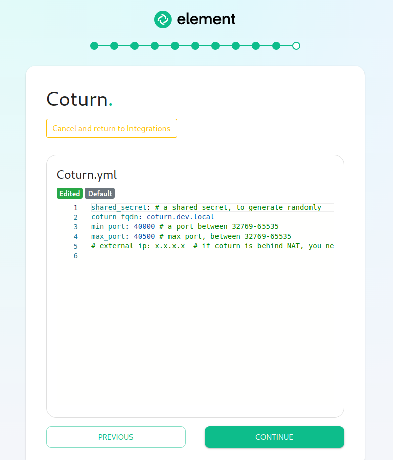
For the coturn.yml presented by the installer, edit the file and ensure the following values are set:
-
coturn_fqdn: The access address to coturn. It should match something likecoturn.<fqdn.tld>. It must resolve to the public-facing IP of the VM. -
shared_secret: A random value, you can generate it withpwgen 32 -
min_port: The minimal UDP Port used by coturn for relaying UDP Packets, in range 32769-65535 -
max_port: The maximum UDP Port used by coturn for relaying UDP Packets, in range 32769-65535
Further, if you are using your own certificates instead of letsencrypt, for the coturn_fqdn, you will need to provide certificates for the installer outside of the GUI. Please find your ~/.element-enterprise-server/config directory and create a directory called ~/.element-enterprise-server/config/legacy/certs under which to put a .crt/.key PEM encoded certificate for this fqdn. If your fqdn was coturn.airgap.local, your filenames would need to be coturn.airgap.local.crt and coturn.airgap.local.key. You will need to have these certificate files in place before running the installer.
Jitsi
From the Installer's Integrations page, click "Install" under "Jitsi".
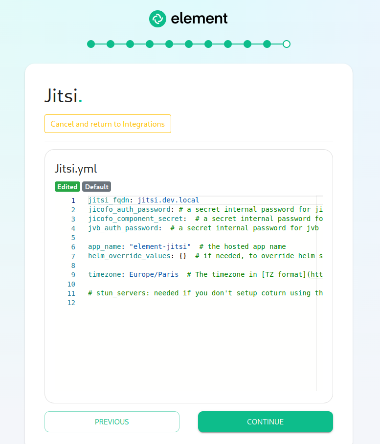
For the jitsi.yml presented by the installer, edit the file and ensure the following values are set:
-
jitsi_fqdn: The access address to jitsi. It should match something likejitsi.<fqdn.tld>. It must resolve to the public-facing IP of the VM. -
jicofo_auth_password: # a secret internal password for jicofo auth -
jicofo_component_secret: # a secret internal password for jicofo component -
jvb_auth_password: # a secret internal password for jvb -
helm_override_values: {} # if needed, to override helm settings automatically set by the installer; For Helm values that can be overriden, see https://vector-im.github.io/jitsi-helm/ For environment variables that can be passed in via Helm overrides, see https://jitsi.github.io/handbook/docs/devops-guide/devops-guide-docker/ -
timezone: Europe/Paris # The timezone in TZ format -
stun_servers: Needed if you don't setup coturn using the installer. Should be a yaml list of server:port entries. Example:stun_servers: - ip:port - ip:port
Further, for the jitsi_fqdn, you will need to provide .crt/.key PEM encoded certificates. These can be entered in the installer UI. If your fqdn was jitsi.airgap.local, your filenames would need to be jitsi.airgap.local.crt and jitsi.airgap.local.key. You will need to edit the file name field in the UI before pressing "Choose File" button when selecting the certificates.
If your network does not have any NAT, Jitsi cannot use the local coturn server to determine the IP it should advertise to the users. In this case, you might have issues with your calls and video. To workaround it, you can use the following configuration :
provide_node_address_as_public_ip: true

helm_override_values:
  jvb:
    extraEnvs:
    - name: JVB_ADVERTISE_IPS
      value:  "public ip of jitsi"
    - name: JVB_ADVERTISE_PRIVATE_CANDIDATES
      value: "true"
Element
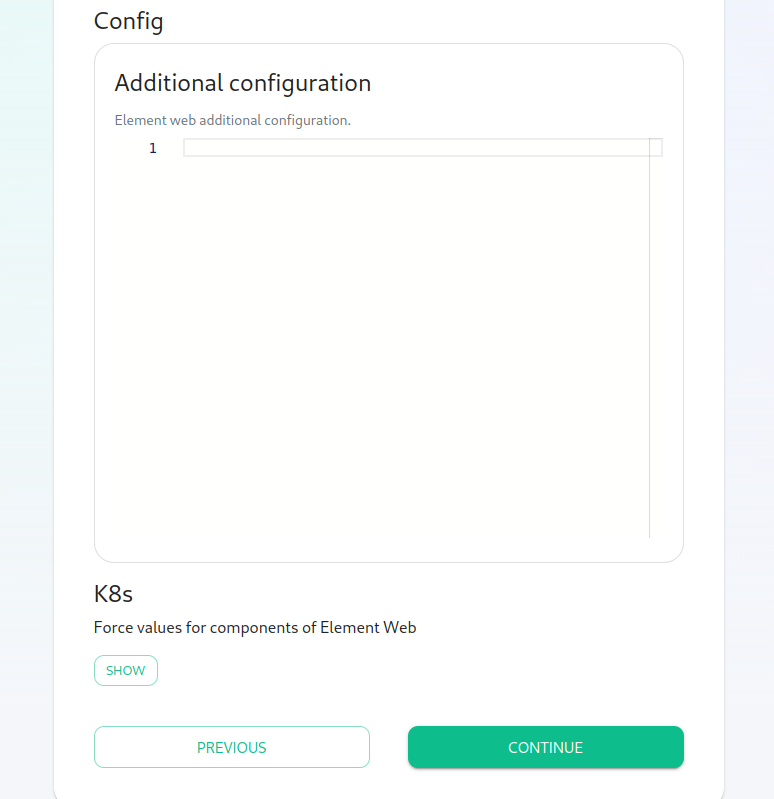
Please go to the "Element Web" page of the installer, click on "Advanced" and add the following to "Additional Configuration":
{
  "jitsi": {
    "preferred_domain": "<jitsi_fqdn>"
  }
}
In the above text, you will want to replace <jitsi_fqdn> with the actual fqdn.
Configure the installer to use an existing Jitsi instance
Please go to the "Element Web" page of the installer, click on "Advanced" and add the following to "Additional Configuration":
{
      "jitsi": {
            "preferred_domain": "your.jitsi.example.org"
      }
}
replacing your.jitsi.example.org with the hostname of your Jitsi server.
You will need to re-run the installer for this change to take effect.
Setting up Group Sync with the Installer
What is Group Sync?
Group Sync allows you to use the ACLs from your identity infrastructure in order to set up permissions on Spaces and Rooms in the Element Ecosystem. Please note that the initial version we are providing only supports a single node, non-federated configuration.
Configuring Group Sync
From the Installer's Integrations page, click "Install" under "Group Sync".
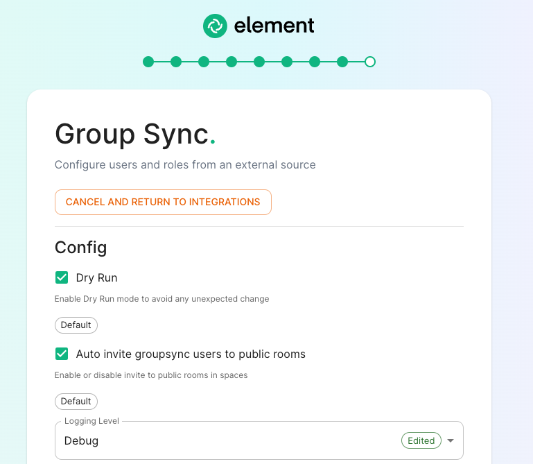
- Leaving
Dry Runchecked in combination withLogging Levelset toDebuggives you the ability to visualize in the pod's log file what result group sync will produce without effectively creating spaces and potentially corrupting your database. Otherwise, uncheckDry Runto create spaces according to your spaces mappings defined in theSpace mappingsection. -
Auto invite groupsync users to public roomdetermines whether users will be automatically invited to rooms (default, public and space-joinable). Users will still get invited to spaces regardless of this setting.
Configuring the source
LDAP Servers
- You should create a LDAP account with read access.
- This account should use password authentication.
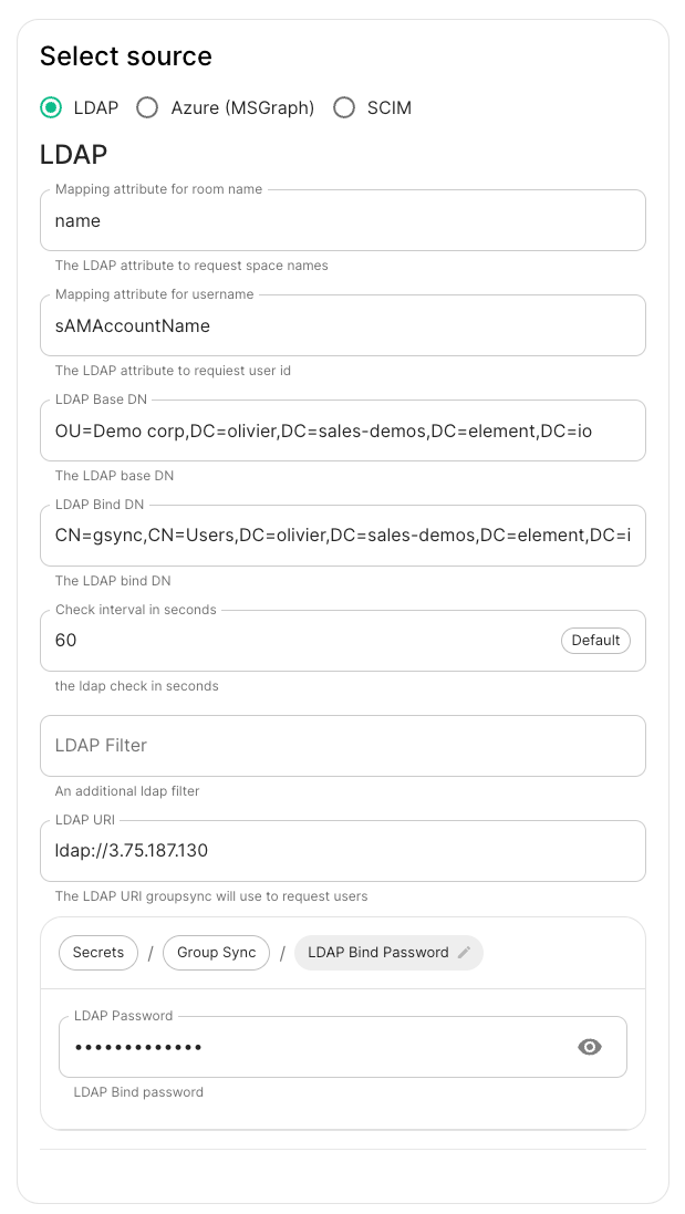
-
LDAP Base DN: the distinguished name of the root level Org Unit in your LDAP directory. In our example,Demo Corpis our root level, spaces are mapped against Org Units , but you can map a space against any object (groups, security groups,..) belonging to this root level. The root level must contain all the Users, Groups and OUs used in the space mapping.
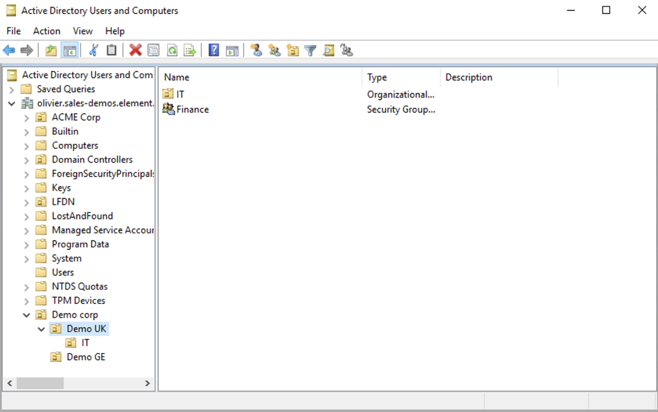
The distinguished name can be displayed by selecting View/Advanced Features in the Active Directory console and then, right-clicking on the object, selecting Properties/Attributes Editor.
The DN is OU=Demo corp,DC=olivier,DC=sales-demos,DC=element,DC=io.
-
Mapping attribute for room name: LDAP attribute used to give an internal ID to the space (visible when setting the log in debug mode) -
Mapping attribute for username: LDAP attribute likesAMAccountNameused to map the localpart of the mxid against the value of this attribute.If
@bob:my-domain.orgis the mxid,bobis the localpart and groupsync expects to match this value in the LDAP attributesAMAccountName. -
LDAP Bind DN: the distinguished name of the LDAP account with read access. -
Check interval in seconds: the frequency Group sync refreshes the space mapping in Element. -
LDAP Filter: an LDAP filter to filter out objects under the LDAP Base DN. The filter must be able to capture Users, Groups and OUs used in the space mapping. -
LDAP URI: the URI of your LDAP server. -
LDAP Bind Password: the password of the LDAP account with read access.
MS Graph (Azure AD)
-
You need to create an
App registration. You'll need theTenant IDof the organization, theApplication (client ID)and a secret generated fromCertificates & secretson the app. -
For the bridge to be able to operate correctly, navigate to API permissions and ensure it has access to Group.Read.All, GroupMember.Read.All and User.Read.All. Ensure that these are Application permissions (rather than Delegated).
-
Remember to grant the admin consent for those.
-
To use MSGraph source, select MSGraph as your source.
-
msgraph_tenant_id: This is the "Tenant ID" from your Azure Active Directory Overview -
msgraph_client_id: Register your app in "App registrations". This will be its "Application (client) ID" -
msgraph_client_secret: Go to "Certificates & secrets", and click on "New client secret". This will be the "Value" of the created secret (not the "Secret ID").
-
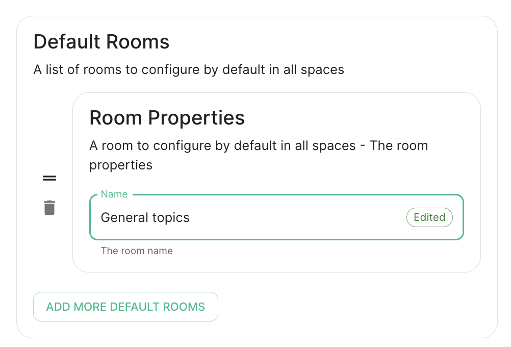
Space Mapping
The space mapping mechanism allows us to configure spaces that Group Sync will maintain, beyond the ones that you can create manually.
It is optional – the configuration can be skipped but if you enable Group Sync, you have to edit the Space mapping by clicking on the EDIT button and rename the (unnamed space)to something meaningful.
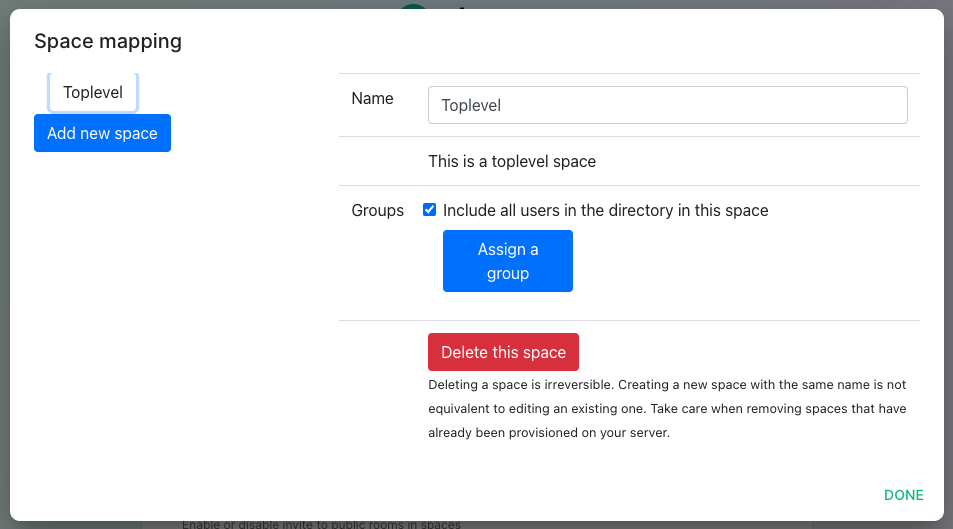
Include all users in the directory in this space: all available users, regardless of group memberships join the space. This option is convenient when creating a common subspace shared between all users.
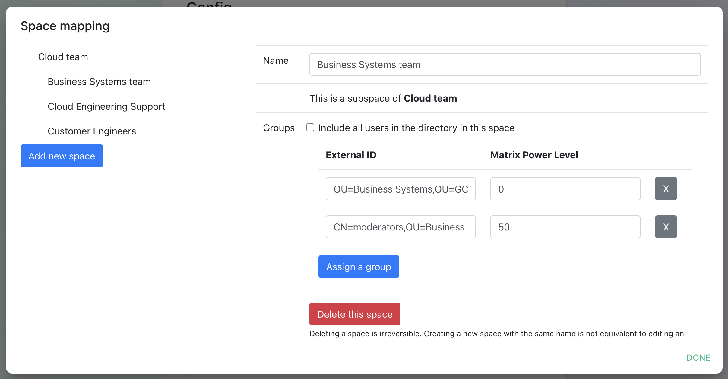
Add new space, you can leave the space as a top level space or you can drag and drop this space onto an existing space, making this space a subspace of the existing space.You can then map an external ID (the LDAP distinguished name) against a power level. Every user belonging to this external ID is granted the power level set in the interface. This external ID that can be any LDAP object like an OrgUnit, a Group or a Security Group. The external ID is case-sensitive
A power level 0 is a default user that can write messages, react to messages and delete his own messages.
A power level 50 is a moderator that can creates rooms, delete messages from members.
A power level 100 is an administrator but since GroupSync manages spaces, invitations to the rooms, it does not make sense to map a group against a power level 100.
Custom power levels other than 0 and 50 are not supported yet.
Users allowed in every GroupSync room
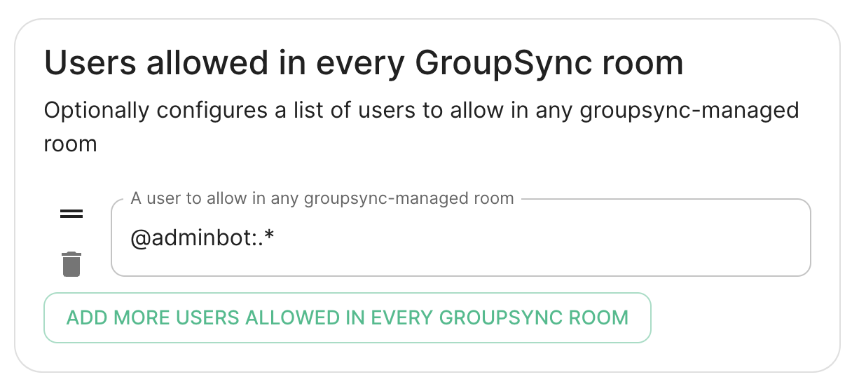
A list of userid patterns that will not get kicked from rooms even if they don't belong to them according to LDAP.
This is useful for things like auditbot if Audibot has been enabled.
Patterns listed here will be wrapped in ^ and $ before matching.
Defaults Rooms
H
Setting up GitLab, GitHub, JIRA and Webhooks Integrations With the Installer
In Element Server Suite, our GitLab, GitHub, and JIRA extensions are provided by the hookshot package. This documentation explains how to configure hookshot.
Configuring Hookshot with the Installer
From the Installer's Integrations page, click "Install" under "Hookshot: Github, Gitlab, Jira, and Custom Webhooks."
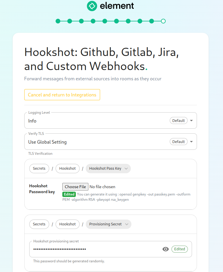
On the first screen here, we can set the logging level and a hookshot specific verify tls setting. Most users can leave these alone.
To use hookshot, you will need to generate a hookshot password key, when can be done by running the following command on a Linux command line:
openssl genpkey -out passkey.pem -outform PEM -algorithm RSA -pkeyopt rsa_keygen_bits:4096
which will generate output similar to this:
..................................................................................................................................................................++++
......................................................................................++++
Once this has finished, you will have a file called passkey.pem that can use to upload as the "Hookshot Password key".
If you wish to change the hookshot provisioning secret, you can, but you can also leave this alone as it is randomly generated by the installer.
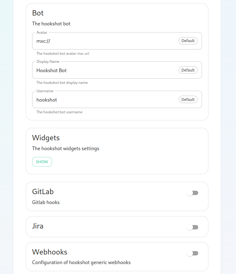
Next, we get to a set of settings that allow us to make changes to the Hookshot bot's appearance.
There is also a button to show widget settings, which brings up these options:
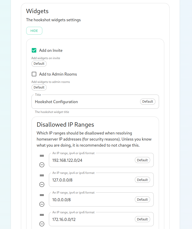
In this form, we have the ability to control how widgets are incorporated into rooms (the defaults are usually fine) and to set a list of Disallowed IP ranges wherein widgets will not load if the homeserver IP falls in the range. If your homeservers IP falls in any of these ranges, you will want to remove that range so that the widgets will load!
Next, we have the option to enable Gitlab, which shows us the following settings:
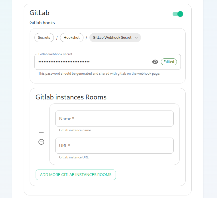
The webhook secret is randomly generated and does not need to be changed. You can also add Gitlab instances by specifying an instance name and pasting the URL.
Next, we have the option to enable Jira, which shows us the following settings:
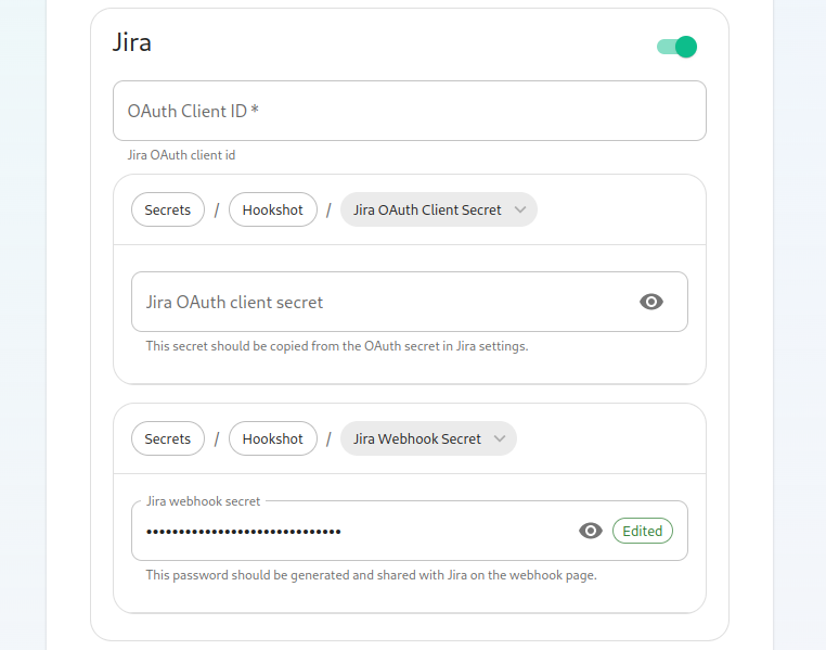
In here, we can specify the OAuth Client ID and the OAuth client secret to connect to Jira. To obtain this information, please follow these steps:
The JIRA service currently only supports atlassian.com (JIRA SaaS) when handling user authentication. Support for on-prem deployments is hoping to land soon.
- You'll first need to head to https://developer.atlassian.com/console/myapps/create-3lo-app/ to create a "OAuth 2.0 (3LO)" integration.
- Once named and created, you will need to:
- Enable the User REST, JIRA Platform REST and User Identity APIs under Permissions.
- Use rotating tokens under Authorisation.
- Set a callback url. This will be the public URL to hookshot with a path of /jira/oauth.
- Copy the client ID and Secret from Settings
Once you've set these, you'll notice that a webhook secret has been randomly generated for you. You can leave this alone or edit it if you desire.
Next, let's look at configuring Webhooks:
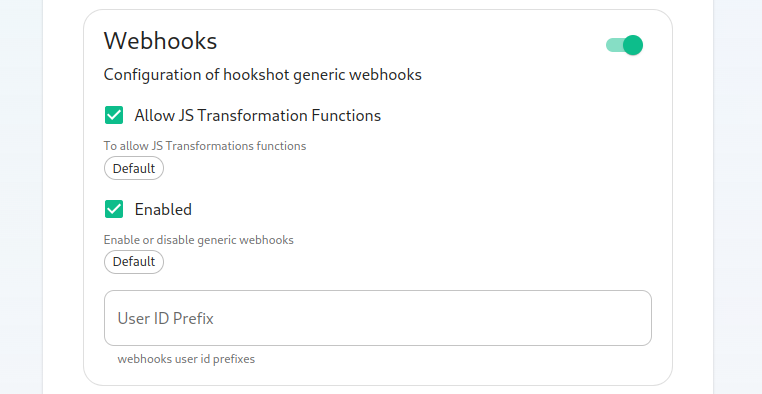
You can set whether or not webhooks are enabled and whether they allow JS Transformation functions. It is good to leave these enabled per the defaults. You can also specify the user id prefix for the creation of custom webhooks. If you set this to webhook_ then each new webhook will appear in a room with a username starting with webhook_.
Next, let's look at configuring Github:
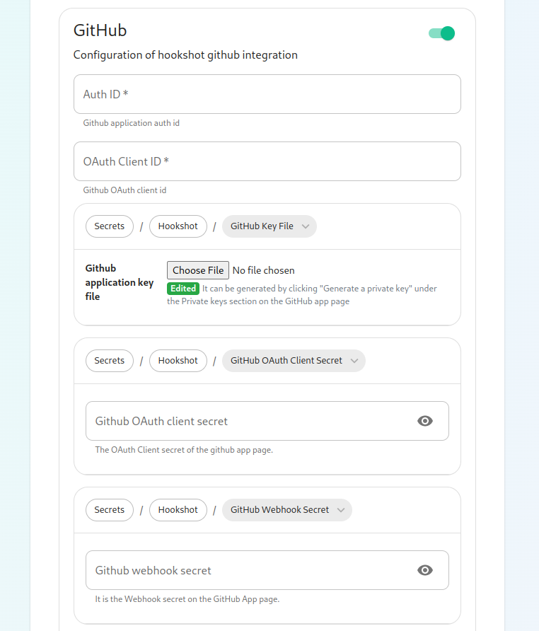
This bridge requires a GitHub App. You will need to create one. Once you have created this, you'll be able to fill in the Auth ID and OAuth Client ID. You will also need to generate a "Github application key file" to upload this. Further, you will need to specify a "Github OAuth client secret" and a "Github webhook secret", both of which will appear on your newly created Github app page.

On this screen, we have the option to change how we call the bot and other minor settings. We also have the ability to select which hooks we provide notifications for, what labels we wish to exclude, and then which hooks we will ignore completely.

Now we have the ability to add a list of labels that we want to match. This has the impact of the integration only notifying you of issues with a specifc set of labels.
We then have the ability to add a list of labels that all newly created issues through the bot should be labeled with.
Then we have the ability to enable showing diffs in the room when a PR is created.
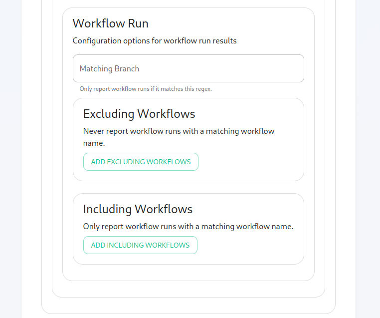
Moving along, we can configure how workflow run results are configured in the bot, including matching specific workflows and including or excluding specific workflows.
Finishing Configuration
You furrther have the ability to click "Advanced" and set any kubernetes specific settings for how this pod is run. Once you have set everything up on this page, you can click "Continue" to go back to the Integrations page.
When you have finished running the installer and the hookshot pod is up and running, there are some configurations to handle in the Element client itself in the rooms that you wish the integration to be present.
As an admin, you will need to enable hookshot in the rooms using the "Add widgets, bridges, & bots" functionality to add the "Hookshot" widget to the room and finish the setup.
Setting up Adminbot and Auditbot
Overview
Adminbot allows for an Element Administrator to become admin in any existing room or space on a managed homeserver. This enables you to delete rooms for which the room administrator has left your company and other useful administration actions.
Auditbot allows you to have the ability to export any communications in any room that the auditbot is a member of, even if encryption is in use. This is important in enabling you to handle compliance requirements that require chat histories be obtainable.
On using Admin Bot and Audit Bot
Currently, we deploy a special version of Element Web to allow you to log in as the adminbot and auditbot. Given this, please do not make changes to widgets in rooms while logged in as the adminbot or the auditbot. The special Element Web does not have any custom settings that you have applied to the main Element Web that your users use and as such, you can cause problems for yourself by working with widgets as the adminbot and auditbot. In the future, we are working to provide custom interfaces for these bots.
Configuring Admin Bot
From the Installer's Integrations page, click "Install" under "Admin Bot"
You will then see the following:
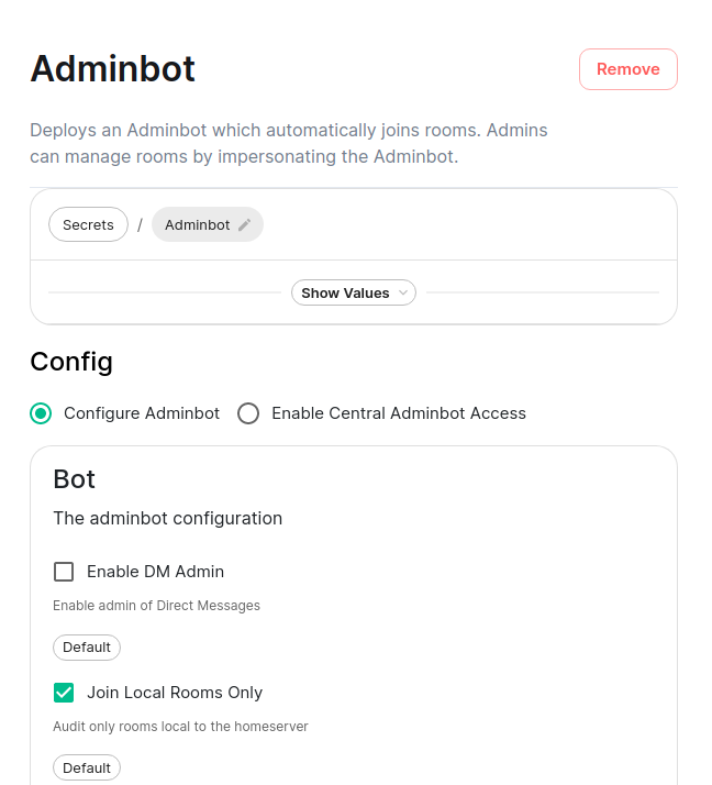
Your first choice is to configure adminbot or enable this server as part of a federated adminbot cluster. For most cases, you'll want to select "Configure Adminbot".
Below this, we have a checkbox to either allow the adminbot to participate in DM rooms (rooms with 1-2 people) or not.
We also have a checkbox to join local rooms only. You probably want to leave this on. If you turn it off, the adminbot will try to join any federated rooms that your server is joined to.
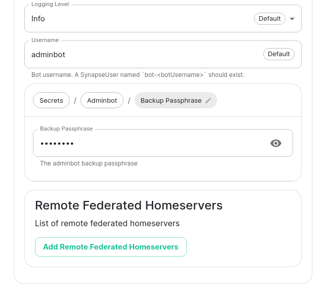
Moving on, we also have the ability to change the logging level and set the username of the bot.
After this, we have the ability to set the "Backup Passphrase" which is used to gain access to the key backup store.
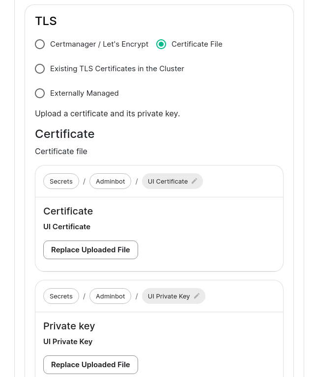
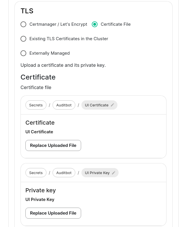
Two settings that need to be set in the "Advanced" section are the fqdn for the adminbot element web access point and its certifactes. These settings can be found by clicking "Advanced" and scrolling to:

and then:
Configuring Audit Bot
From the Installer's Integrations page, click "Install" under "Audit Bot".
You will then see the following:
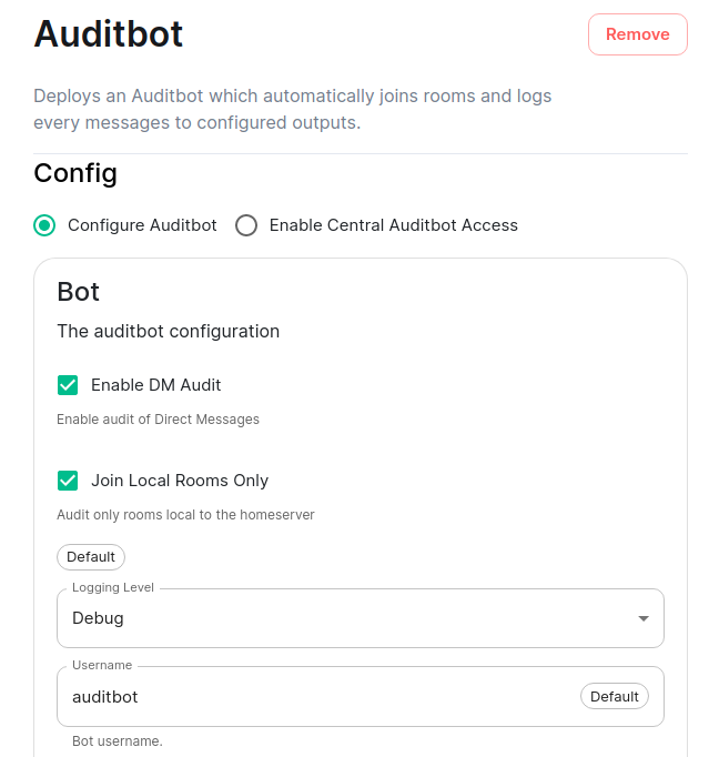

Your first choice is to configure auditbot or enable this server as part of a federated auditbot cluster. For most cases, you'll want to select "Configure Auditbot".
Below this, we have a checkbox to either allow the adminbot to participate in DM rooms (rooms with 1-2 people) or not.
We also have a checkbox to join local rooms only. You probably want to leave this on. If you turn it off, the adminbot will try to join any federated rooms that your server is joined to.
Moving on, we also have the ability to change the logging level and set the username of the bot.
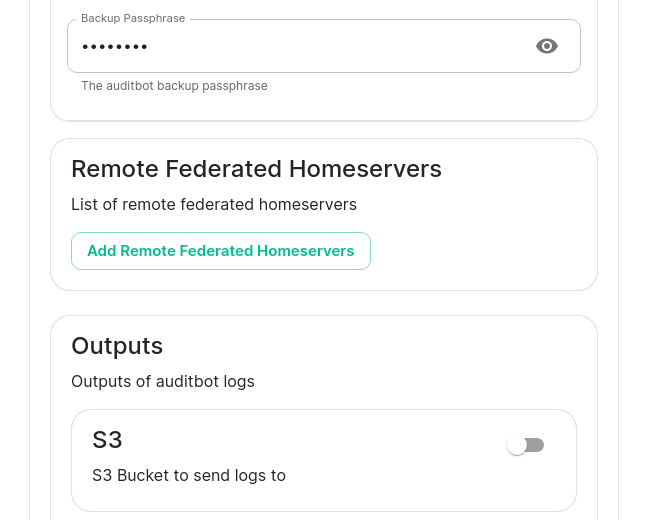
After this, we have the ability to set the "Backup Passphrase" which is used to gain access to the key backup store.
You can also configure an S3 bucket to log to and you can configure how many logfiles should be kept and how large a log file should be allowed to grow to. By default, the auditbot will log to the storage that has been attached by the cluster (check the storage settings under the "Advanced" tab).
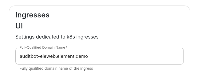
Two settings that need to be set in the "Advanced" section are the fqdn for the auditbot element web access point and its certifactes. These settings can be found by clicking "Advanced" and scrolling to:
Adminbot Federation
On the central admin bot server
You will pick "Configure Admin Bot" and will fill in everything from the above Adminbot configuration instructions, but you will also add Remote Federated Homeservers in this interface:
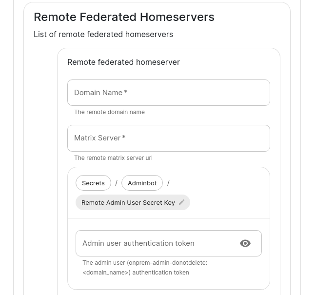
You will need to fill out this form for each remote server that will join the federation. You will need to set the domain name and the matrix server for each to get started.
You will also need to grab the Admin user authentication token for each server and specify that here. You may get this with the following command run against a specific server: kubectl get synapseusers/adminuser-donotdelete -n element-onprem -o yaml. You are looking for the value of the field status.accessToken.
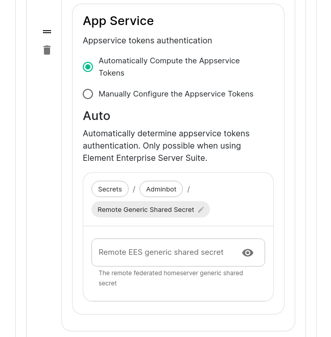
Then in the app service, you can leave Automatically compute the appservice tokens set. You will need to also get the generic shared secret from that server and specify it here as well. You can get this value from running: kubectl get -n element-onprem secrets first-element-deployment-synapse-secrets -o yaml | grep registration and looking at the value for the registrationSharedSecret.
On the remote admin bot server
Instead of selecting "Configure Adminbot", you will pick "Enable Central Adminbot Access" and will then be presented with this UI:
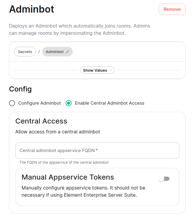
You will then specify the FQDN of the central adminbot server.
Auditbot Federation
On the central auditbot server
You will pick "Configure Audit Bot" and will fill in everything from the above Auditbot configuration instructions, but you will also add Remote Federated Homeservers in this interface:
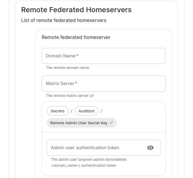

You will need to fill out this form for each remote server that will join the federation. You will need to set the domain name and the matrix server for each to get started.
You will also need to grab the Admin user authentication token for each server and specify that here. You may get this with the following command run against a specific server: kubectl get synapseusers/adminuser-donotdelete -n element-onprem -o yaml. You are looking for the value of the field status.accessToken.
Then in the app service, you can leave Automatically compute the appservice tokens set. You will need to also get the generic shared secret from that server and specify it here as well. You can get this value from running: kubectl get -n element-onprem secrets first-element-deployment-synapse-secrets -o yaml | grep registration and looking at the value for the registrationSharedSecret.
On the remote audit bot server
Instead of selecting "Configure Auditbot", you will pick "Enable Central Auditbot Access" and will then be presented with this UI:
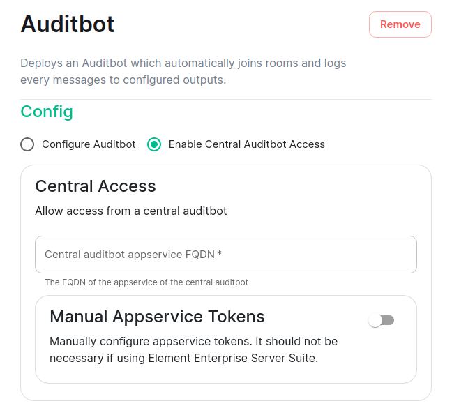
You will then specify the FQDN of the central auditbot server.
Setting Up Hydrogen
Configuring Hydrogen
From the Installer's Integrations page, click "Install" under "Hydrogen".
For the hydrogen.yml presented by the installer, edit the file and ensure the following values are set:
-
hydrogen_fqdnis the FQDN that will be used for accessing hydrogen. It must have a PEM formatted SSL certificate as mentioned in the introduction. The crt/key pair must be in theCONFIG_DIRECTORY/certsdirectory. -
extra_configis extra json config that should be injected into the hydrogen client configuration.
You will need to re-run the installer after making these changes for them to take effect.
Setting up On-Premise Metrics
Setting up VictoriaMetrics and Grafana
From the Installer's Integrations page, click "Install" under "Monitoring"
For the provided prom.yml, see the following descriptions of the parameters:
-
If you want to write prometheus data to a remote prometheus instance, please define these 4 variables :
-
remote_write_url: The URL of the endpoint to which to push remote writes -
remote_write_external_labels: The labels to add to your data, to identify the writes from this cluster -
remote_write_username: The username to use to push the writes -
remote_write_password: The password to use to push the writes
-
-
You can configure which prometheus components you want to deploy :
-
deploy_vmsingle,deploy_vmagentanddeploy_vmoperator:trueto deploy VictoriaMetrics -
deploy_node_exporter: requires prometheus deployment. Set totrueto gather data about the k8s nodes. -
deploy_kube_control_plane_monitoring: requires prometheus deployment. Set totrueto gather data about the kube controle plane. -
deploy_kube_state_metrics: requires prometheus deployment. Set totrueto gather data about kube metrics. -
deploy_element_service_monitors: Set totrueto createServiceMonitorresources into the K8S cluster. Set it totrueif you want to monitor your element services stack using prometheus. -
You can choose to deploy grafana on the cluster :
-
deploy_grafana:true -
grafana_fqdn: The FQDN of the grafana application -
grafana_data_path:/mnt/data/grafana -
grafana_data_size: 1G
-
For the specified grafana_fqdn, you will need to provide a crt/key PEM encoded key pair in ~/.element-enterprise-server/config/legacy/certs prior to running the installer. If our hostname were metrics.airgap.local, the installer will expect to find metrics.airgap.local.crt and metrics.airgap.local.key in the ~/.element-enterprise-server/config/legacy/certs` directory. If you are using Let's Encrypt, you do not need to add these files.
After running the installer, open the FQDN of Grafana. The initial login user is admin and password is the value of admin_password. You'll be required to set a new password, please define one secured and keep it in a safe place.
~
Setting Up the Telegram Bridge
Configuring Telegram bridge
On Telegram platform
- Login to my.telegram.org to get a telegram app ID and hash (get from ). You should use a phone number associated to your company.
Basic config
From the Installer's Integrations page, click "Install" under "Telegram Bridge".
For the provided telegram.yml file, please see the following options:
-
postgres_create_in_cluster:trueto create the postgres db into the k8s cluster. On a standalone deployment, it is necessary to define thepostgres_data_path. -
postgres_fqdn: The fqdn of the postgres server. If usingpostgres_create_in_cluster, you can choose the name of the workload. -
postgres_data_path: "/mnt/data/telegram-postgres" -
postgres_port: 5432 -
postgres_user: The user to connect to the db. -
postgres_db: The name of the db. -
postgres_password: A password to connect to the db. -
telegram_fqdn: The FQDN of the bridge for communicating with Telegram and using public login user interface. -
max_users: Max number of users enabled on the bridge. -
bot_username: The username of the bot for users to manage their bridge connectivity. -
bot_display_name: The display name of the bot. -
bot_avatar: An mx content URL to the bot avatar. -
admins: The list of admins of the bridge. -
enable_encryption: true to allow e2e encryption in bridge. -
enable_encryption_by_default: true to enable by default e2e encryption on every chat created by the bridge. -
enable_public_portal: true to give the possibility to users to login using the bridge portal UI. -
telegram_api_id: The telegram API ID you got from telegram platform. -
telegram_api_hash: The telegram api hash you got from telegram platform.
For the specified telegram_fqdn, you will need to provide a crt/key PEM encoded key pair in ~/.element-enterprise-server/config/legacy/certs prior to running the installer. If our hostname were telegram.airgap.local, the installer will expect to find telegram.airgap.local.crt and telegram.airgap.local.key in the ~/.element-enterprise-server/config/legacy/certs` directory. If you are using Let's Encrypt, you do not need to add these files.
You will need to re-run the installer after making changes for these to take effect.
Usage
- Talk to the telegram bot to login to the bridge. See Telegram Bridge starting at "Bridge Telegram to your Element account". Instead of addressing the bot as that document explains, use "@bot_username:domain" as per your setup.
Setting Up the Teams Bridge
Configuring Teams Bridge
Register with Microsoft Azure
You will first need to generate an "Application" to serve connect your Teams bridge with Microsoft.
- Connect to Azure on https://portal.azure.com/#blade/Microsoft_AAD_IAM/ActiveDirectoryMenuBlade/Overview to go to the Active Directory.
- Go to "Register an application screen" and register an application.
- Supported account types can be what fits your needs, but do not select "Personal Microsoft accounts"
-
Redirect URI must be
https://<teams_fqdn>/authenticate. You must use the typeDesktop and Mobile apps. You don't need to check any of suggested redirection URIs. - You should be taken to a general configuration page. Click Certificates & secrets
- Generate a Client Secret and copy the resulting value. The value will be your
teams_client_secret.
Permissions
You will need to set some API permissions.
For each of the list below click Add permission > Microsoft Graph > and then set the Delegated permissions.
- ChannelMessage.Read.All - Delegated
- ChannelMessage.Send - Delegated
- ChatMessage.Read - Delegated
- ChatMessage.Send - Delegated
- ChatMember.Read - Delegated
- ChatMember.ReadWrite - Delegated
- Group.ReadWrite.All - Delegated
- offline_access - Delegated
- profile - Delegated
- Team.ReadBasic.All - Delegated
- User.Read - Delegated
- User.Read.All - Delegated
For each of the list below click Add permission > Microsoft Graph > and then set the Application permissions:
- ChannelMember.Read.All - Application
- ChannelMessage.Read.All - Application
- Chat.Create - Application
- Chat.Read.All - Application
- Chat.ReadBasic.All - Application
- Chat.ReadWrite.All - Application
- ChatMember.Read.All - Application
- ChatMember.ReadWrite.All - Application
- ChatMessage.Read.All - Application
- Group.Create - Application
- Group.Read.All - Application
- Group.ReadWrite.All - Application
- GroupMember.Read.All - Application
- GroupMember.ReadWrite.All - Application
- User.Read.All - Application
Once you are done, click Grant admin consent
-
Go to Overview
-
Copy the "Application (client) ID" as your
teams_client_idin the config -
Copy the "Directory (tenant) ID" as the
teams_tenant_idin the config.
Setting up the bot user
The bridge requires a Teams user to be registered as a "bot" to send messages on behalf of Matrix users. You just need to allocate one user from the Teams interface to do this.
- First, you must go to the Azure Active Directory page.
- Click users.
- Click New user.
- Ensure Create user is selected.
- Enter a User name ex. "matrixbridge".
- Enter a Name ex. "Matrix Bridge".
- Enter an Initial password.
- Create the user.
- Optionally, set more profile details like an avatar.
- You will now need to log in as this new bot user to set a permanent password (Teams requires you to reset the password on login).
- After logging in you should be prompted to set a new password.
- Enter the bot username and password into config under
teams_bot_usernameandteams_bot_password
Getting the groupId
The groupId can be found by opening Teams, clicking ... on a team, and clicking "Get link to team". The groupId is included in the URL 12345678-abcd-efgh-ijkl-lmnopqrstuvw in this example.
https://teams.microsoft.com/l/team/19%3XXX%40thread.tacv2/conversations?groupId=12345678-abcd-efgh-ijkl-lmnopqrstuvw&tenantId=87654321-dcba-hgfe-lkji-zyxwvutsrqpo
On the hosting machine
Generate teams registration keys
openssl genrsa -out teams.key 1024
openssl req -new -x509 -key teams.key -out teams.crt -days 365
These keys need to be placed in ~/.element-enterprise-server/config/legacy/certs/teams on the machine that you are running the installer on.
Configure Teams Bridge
From the Installer's Integrations page, click "Install" under "Microsoft Teams Bridge"
For the provided teams.yml, please the following documentation of the parameters:
teams_client_id: # teams app client id
teams_client_secret: # teams app secret
teams_tenant_id: # teams app tenant id
teams_bot_username: # teams bot username
teams_bot_password: # teams bot password
teams_cert_file: teams.crt
teams_cert_private: teams.key
teams_fqdn: <teams bridge fqdn>
teams_bridged_groups:
- group_id: 218b0bfe-05d3-4a63-8323-846d189f1dc1 #change me
  properties:
    autoCreateRooms:
      public: true
      powerLevelContent:
        users:
          "@alice:example.com": 100 # This will add <alice> account as admin
          "@teams-bot:example.com": 100 # the Teams bot mxid <bot_sender_localpart>:<domain_name>
    autoCreateSpace: true
    limits:
      maxChannels: 25
      maxTeamsUsers: 25
# repeat "- group_id:" section above for each Team you want to bridge


bot_display_name: Teams Bridge Bot
bot_sender_localpart: teams-bot
enable_welcome_room: true
welcome_room_text: |
 Welcome, your Element host is configured to bridge to a Teams instance.

 This means that Microsoft Teams messages will appear on your Element
 account and you can send messages in Element rooms to have them appear
 on teams.

 To allow Element to access your Teams account, please say `login` and
 follow the steps to get connected. Once you are connected, you can open
 the 🧭 Explore Rooms dialog to find your Teams rooms.
# namespaces_prefix_user: OPTIONAL: default to _teams_
# namespaces_prefix_aliases: OPTIONAL: default to teams_
- For each Bridged Group, you will need to set a group_id and some properties found in the config sample.
You will need to re-run the installer for changes to take effect.
Setting Up the IRC Bridge
Matrix IRC Bridge
The Matrix IRC Bridge is an IRC bridge for Matrix that will pass all IRC messages through to Matrix, and all Matrix messages through to IRC. Please also refer to the bridges' specific documentation for additional guidance.
For usage of the IRC Bridge via it's bot user see Using the Matrix IRC Bridge documentation.
Installation and Configuration
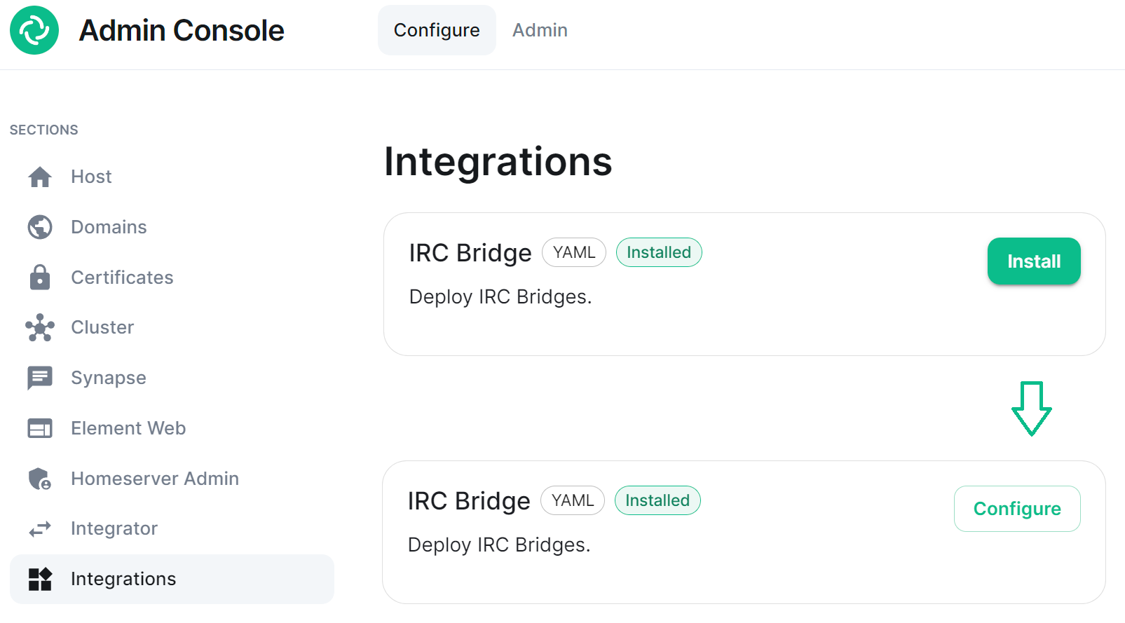
From the Installer's Integrations page find the IRC Bridge entry, and click Install.This will setup the IRC Bridges' config directory, by default this will be located:
~/.element-enterprise-server/config/legacy/ircbridge
You will initially be taken to the bridges configuration page, for any subsequent edits, the Install button will be replaced with Configure, indicating the bridge is installed.
There are two sections of the Matrix IRC Bridge configuration page, the Bridge.yml section, and a section to Upload a Private Key. We'll start with the latter as it's the simplest of the two, and is referenced in the first.
Upload a Private Key
As the bridge needs to send plaintext passwords to the IRC server, it cannot send a password hash, so those passwords are stored encrypted in the bridge database. When a user specifies a password to use, using the admin room command !storepass server.name passw0rd, the password is encrypted using a RSA PEM-formatted private key. When a connection is made to IRC on behalf of the Matrix user, this password will be sent as the server password (PASS command).
Therefore you will need a Private Key file, by default called passkey.pem:
-
If you have a Private Key file already, simply upload the file using this sections
Upload Filebutton, supplying a RSA PEM-formatted private key.

-
If you don't already have one, per the instructions provided in the section itself, you should generate this file by running the following command from within the IRC Bridges' config directory:
penssl genpkey -out passkey.pem -outform PEM -algorithm RSA -pkeyopt rsa_keygen_bits:2048

The Bridge.yml Section
The Bridge.yml is the complete configuration of the Matrix IRC Bridge. It points to a private key file (Private Key Settings), and both configures the bridges' own settings and functionality (Bridge Settings), and the specific IRC services you want it to connect with (IRC Settings).
Private Key Settings
key_file: passkey.pem
By default this is the first line in the Bridge.yml config, it refers to the file either moved into the IRC Bridges' config directory, or generated in there using openssl. If moved into the directory ensure the file was correctly renamed to passkey.pem.
Bridge Settings
The rest of the configuration sits under the bridged_irc_servers: section:
bridged_irc_servers:
You'll notice all entries within are initially indented ( ) so all code blocks will include this indentation. Focusing on settings relating to the bridge itself (and not any specific IRC connection) covers everything except the address: and associated parameters: sections, by default found at the end of the Bridge.yml.
Postgres
If you are using postgres-create-in-cluster you can leave this section as-is, the default ircbridge-postgres / ircbridge / postgres_password values will ensure your setup works correctly.
- postgres_fqdn: ircbridge-postgres
  postgres_user: ircbridge
  postgres_db: ircbridge
  postgres_password: postgres_password
Otherwise you should edit as needed to connect to your existing Postgres setup:
-
postgres_fqdn:Provide the URL to your Postgres setup -
postgres_user:Provide the user that will be used to connect to the database -
postgres_db:Provide the database you will connect to -
postgres_password:Provide the password of the user specified above
You can uncomment the following to use as needed, note if unspecified some of these will default to the advised values, you do not need to uncomment if you are happy with the defaults.
-
postgres_data_path:This can be used to specify the path to the postgres db on the host machine -
postgres_port:This can be used to specify a non-standard port, this defaults to5432. -
postgres_sslmode:This can be used to specify the sslmode for the Postgres connection, this defaults to'disable', however'no-verify'and'verify-fullare available options
For example, your Postgres section might instead look like the below:
- postgres_fqdn: https://db.example.com
  postgres_user: example-user
  postgres_db: matrixircbridge
  postgres_password: example-password
  # postgres_data_path: "/mnt/data/<bridged>-postgres"
  postgres_port: 2345
  postgres_sslmode: 'verify-full'
IRC Bridge Admins
Within the admins: section you will need to list all the Matrix User ID's of your users who should be Admins of the IRC Bridge. You should list one Matrix User ID per line using the full Matrix User ID formatted like @USERNAME:HOMESERVER
  admins:
  - "@user-one:example.com"
  - "@user-two:example.com"
Provisioning
Provisioning allows you to set specified rules about existing room when bridging those rooms to IRC Channels.
-
enable_provisioning:Set this totrueto enable the use ofprovisioning_rules: -
provisioning_rules:->userIds:Use Regex to specify which User IDs to check for in existing rooms that are trying to be bridged-
exempt:List any User IDs you do not want to prevent the bridging of a room, that would otherwise meet the match inconflict: -
conflict:Specify individual User IDs, or use Regex
-
-
provisioning_room_limit:Specify the number of channels allowed to be bridged
So the example bridge.yml config below will block the bridging of a room if it has any User IDs within it from the badguys.com homeserver except @doubleagent:badguys.com, and limit the number of bridged rooms to 50.
  enable_provisioning: true
  provisioning_rules:
    userIds:
      exempt:
        - "@doubleagent:badguys.com"
      conflict:
        - "@.*:badguys.com"
  provisioning_room_limit: 50
IRC Ident
If you are using the Ident protocol you can enable it usage with the following config:
-
enable_ident:Set this totrueto enable the use of IRC Ident -
ident_port_type:Specify either'HostPort'or'NodePort'depending on your setup -
ident_port_number:Specify the port number that should be used
  enable_ident: false
  ident_port_type: 'HostPort'
  ident_port_number: 10230
Miscellaneous
Finally there are a few additional options to configure:
-
logging_level:This specifies how detailed the logs should be for the bridge, by default this isinfo, buterror,warnanddebugare available.- You can see the bridge logs using
kubectl logs IRC_POD_NAME -n element-onprem
- You can see the bridge logs using
-
enable_presence:Set totrueif presence is required.- This should be kept as
falseif presence is disabled on the homeserver to avoid excess traffic.
- This should be kept as
-
drop_matrix_messages_after_seconds:Specify after how many seconds the bridge should drop Matrix messages, by default this is0meaning no messages will be dropped.- If the bridge is down for a while, the homeserver will attempt to send all missed events on reconnection. These events may be hours old, which can be confusing to IRC users if they are then bridged. This option allows these old messages to be dropped.
-
CAUTION: This is a very coarse heuristic. Federated homeservers may have different clock times which may be old enough to cause all events from the homeserver to be dropped.
-
bot_username:Specify the Matrix User ID of the the bridge bot that will facilitate the creation of rooms and can be messaged by admins to perform commands.
-
rmau_limit:Set this to the maximum number of remote monthly active users that you would like to allow in a bridged IRC room.
-
users_prefix:Specify the prefix to be used on the Matrix User IDs created for users who are communicating via IRC.
-
alias_prefix:Specify the prefix to be used on room aliases when created via the!joincommand.
The defaults are usually best left as-is unless a specific need requires changing these, however for troubleshooting purposes, switching logging_level to debug can help identify issues with the bridge.
  logging_level: debug
  enable_presence: false
  drop_matrix_messages_after_seconds: 0
  bot_username: "ircbridgebot"
  rmau_limit: 100
  users_prefix: "irc_"
  alias_prefix: "irc_"
Advanced Additional Configuration
You can find more advanced configuration options by checking the config.yaml sample provided on the Matrix IRC Bridge repository.
You can ignore the servers: block as config in that section should be added under the parameters: section associated with address: that will be setup per the below section. If you copy any config, ensure the indentation is correct, as above, all entries within are initially indented ( ), so they are under the bridged_irc_servers: section.
IRC Settings
The final section of Bridge.yml, here you specify the IRC network(s) you want the bridge to connect with, this is done using address: and parameter: formatted like so:
-
address:Specify your desired IRC Network
  address: irc.example.com
  parameters:
Aside from the address of the IRC Network, everything is configured within the parameters: section, and so is initially indented , all code blocks will include this indentation.
Basic IRC Network Configuration
At a minimum, you will need to specify the name: of your IRC Network, as well as some details for the bots configuration on the IRC side of the connection, you can use the below to get up and running.
-
name:The server name to show on the bridge. -
botConfig:-
enabled:Keep this set astrue -
nick:Specify the nickname of the bot user within IRC -
username:Specify the username of the bot user within IRC -
password:Optionally specify the password of the bot to give to NickServ or IRC Server for this nick. You can generate this by using thepwgen 32 1command
-
    name: "Example IRC"
    botConfig:
      enabled: true
      nick: "MatrixBot"
      username: "matrixbot"
      password: "some_password"
Advanced IRC Network Configuration (Load Balancing, SSL, etc.)
For more fine-grained control of the IRC connection, there are some additional configuration lines you may wish to make use of. As these are not required, if unspecified some of these will default to the advised values, you do not need to include any of these if you are happy with the defaults. You can use the below config options, in addition to those in the section above, to get more complex setups up and running.
-
additionalAddresses:Specify any additional addresses to connect to that can be used for load balancing between IRCDs- Specify each additional address within the
[]as comma-separated values, for example:-
[ "irc2.example.com", "irc3.example.com" ]
-
- Specify each additional address within the
-
onlyAdditionalAddresses:Set totrueto exclusively use additional addresses to connect to servers while reserving the main address for identification purposes, this defaults tofalse -
port:Specify the exact port to use for the IRC connection -
ssl:Set totrueto require the use SSL, this defaults tofalse -
sslselfsign:Set totrueif the IRC network is using a self-signed certificate, this defaults tofalse -
sasl:Set totrueshould the connection attempt to identify via SASL, this defaults tofalse -
allowExpiredCerts:Set totrueto allow expired certificates when connecting to the IRC server, this defaults tofalse -
botConfig:-
joinChannelsIfNoUsers:Set tofalseto prevent the bot from joining channels even if there are no Matrix users on the other side of the bridge, this defaults totrueso doesn't need to be specified unlessfalseis required.
-
If you end up needing any of these additional configuration options, your parameters: section may look like the below example:
    name: "Example IRC"
    additionalAddresses: [ "irc2.example.com" ]
    onlyAdditionalAddresses: false
    port: 6697
    ssl: true
    sslselfsign: false
    sasl: false
    allowExpiredCerts: false
    botConfig:
      enabled: true
      nick: "MatrixBot"
      username: "matrixbot"
      password: "some_password"
      joinChannelsIfNoUsers: true
Mapping IRC user modes to Matrix power levels
You can use the configuration below to map the conversion of IRC user modes to Matrix power levels. This enables bridging of IRC ops to Matrix power levels only, it does not enable the reverse. If a user has been given multiple modes, the one that maps to the highest power level will be used.
-
modePowerMap:Populate with a list of IRC user modes and there respective Matrix Power Level in the formate ofIRC_USER_MODE: MATRIX_POWER_LEVEL
    modePowerMap:
      o: 50
      v: 1
Configuring DMs between users
By default private messaging is enabled via the bridge and Matrix Direct Message rooms can be federated. You can customise this behaviour using the privateMessages: config section.
-
enabled:Set tofalseto prevent private messages to be sent to/from IRC/Matrix, defaults totrue -
federate:Set tofalseso only users on the homeserver attached to the bridge to be able to use private message rooms, defaults totrue
    privateMessages:
      enabled: true
      federate: true
Mapping IRC Channels to Matrix Rooms
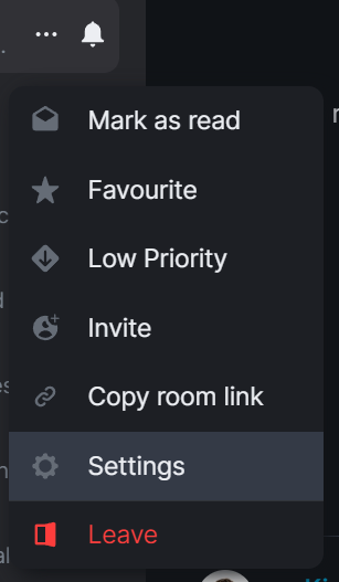
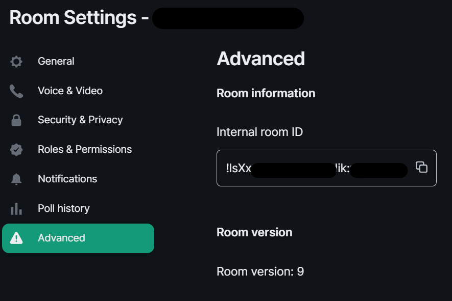
Whilst a user can use the !join command (if Dynamic Channels are enabled) to manually connect to IRC Channels, you can specify mappings of IRC Channels to Matrix Rooms, 1 Channel can be mapped to multiple Matrix Rooms, up-front. The Matrix Room must already exist, and you will need to include it's Room ID within the configuration - you can get this ID by using the 3-dot menu next to the room, and opening Settings.
-
mappings:Under here you will need to specify an IRC Channel, then within that you will need to list out the requiredroomIds:in[]as a comma-separated list and provide akey:if there is a Channel key / password to us. If provided Matrix users do not need to know the channel key in order to join it.mappings: "#IRC_CHANNEL_NAME": roomIds: ["!ROOM_ID_THREE:HOMESERVER", "!ROOM_ID_TWO:HOMESERVER"] key: "secret"
See the below example configuration for mapping the #welcome IRC Channel:
    mappings:
      "#welcome":
        roomIds: ["!exampleroomidhere:example.com"]
Allowing !join with Dynamic Channels
If you would like for users to be able to use the !join command to join any allowed IRC Channel you will need to configure dynamicChannels:.
You may remember you set an alias prefix in the Miscellaneous section above. If you wish to fully customise the format of aliases of bridged rooms you should remove that `alias_prefix:` line. However the only benefit to this would be to add a suffix to the Matrix Room alias so is not recommended.
-
enabled:Set totrueto allow users to use the!joincommand to join any allowed IRC Channel, defaults tofalse -
createAlias:Set tofalseif you do not want an alias to be created for any new Matrix rooms created using!join, defaults totrue -
published:Set tofalseto prevent the created Matrix room via!joinfrom being published to the public room list, defaults totrue -
useHomeserverDirectory:Set totrueto publish room to your Homeservers' directory instead of one created for the IRC Bridge, defaults tofalse -
joinRule:Set to"invite"so only users with an invite can join the created room, otherwise this defaults to"public", so anyone can join the room -
whitelist:Only used ifjoinRule:is set toinvite, populate with a list of Matrix User IDs that the IRC bot will send invites to in response to a!join -
federate:Set tofalseso only users on the homeserver attached to the bridge to be able to use these rooms, defaults totrue -
aliasTemplate:Only used ifcreateAlias:is set totrue. Set to specify the alias for newly created rooms from the!joincommand, defaults to"#irc_$CHANNEL"- You should not include this line if you do not need to add a suffix to your Matrix Room alias. Using
alias_prefix:, this will default to#PREFIX_CHANNEL_NAME:HOMESERVER - If you are specifying this line, you can use the following variables within the alias:
-
$SERVER=> The IRC server address (e.g."irc.example.com") -
$CHANNEL=> The IRC channel (e.g."#python"), this must be used within the alias
-
- You should not include this line if you do not need to add a suffix to your Matrix Room alias. Using
-
exclude:Provide a comma-separated list of IRC Channels within[]that should be prevented from being mapped under any circumstances
In addition you could also specify the below, though it is unlikely you should need to specify the exact Matrix Room Version to use.
-
roomVersion:Set to specify the desired Matrix Room Version, if unspecified, no specific room version is requested.- If the homeserver doesn't support the room version then the request will fail.
    dynamicChannels:
      enabled: true
      createAlias: true
      published: true
      useHomeserverDirectory: true
      joinRule: invite
      federate: true
      aliasTemplate: "#irc_$CHANNEL"
      whitelist:
        - "@foo:example.com"
        - "@bar:example.com"
      exclude: ["#foo", "#bar"]
Exclude users from using the bridge
Using the excludedUsers: configuration you can specify Regex to identify users to be kicked from any IRC Bridged rooms.
-
regex:Set this to any Regex that should match on users' Matrix User IDs -
kickReason:Set to specify the reason provided to users when kicked from IRC Bridged rooms
    excludedUsers:
      - regex: "@.*:evilcorp.com"
        kickReason: "We don't like Evilcorp"
Syncing Matrix and IRC Membership lists
To manage and control how Matrix and IRC membership lists are synced you will need to include membershipLists: within your config.
-
enabled:Set totrueto enable the syncing of membership lists between IRC and Matrix, defaults tofalse- This can have a significant effect on performance on startup as the lists are synced
-
floodDelayMs:Syncing membership lists at startup can result in hundreds of members to process all at once. This timer drip feeds membership entries at the specified rate, defaults to10000(10 Seconds)
Within membershipLists: are the following sections, global:, rooms:, channels: and ignoreIdleUsersOnStartup:. For global:, rooms:, channels: you can specify initial:, incremental: and requireMatrixJoined: which all default to false. You can configure settings globally, using global:, or specific to Matrix Rooms with rooms: or IRC Channels via channels:.
- What does setting
initial:totruedo?- For
ircToMatrix:this gets a snapshot of all real IRC users on a channel (via NAMES) and joins their virtual matrix clients to the room - For
matrixToIrc:this gets a snapshot of all real Matrix users in the room and joins all of them to the mapped IRC channel on startup
- For
- What does setting
incremental:totruedo?- For
ircToMatrix:this makes virtual matrix clients join and leave rooms as their real IRC counterparts join/part channels - For
matrixToIrc:this makes virtual IRC clients join and leave channels as their real Matrix counterparts join/leave rooms
- For
- What does setting
requireMatrixJoined:totruedo?- This controls if the bridge should check if all Matrix users are connected to IRC and joined to the channel before relaying messages into the room. This is considered a safety net to avoid any leakages by the bridge to unconnected users but given it ignores all IRC messages while users are still connecting it's likely not required.
The last section is ignoreIdleUsersOnStartup: which determines if the bridge should ignore users which are not considered active on the bridge during startup.
-
enabled:Set totrueto allow ignoring of idle users during startup -
idleForHours:Set to configure how many hours a user has to be idle for before they can be ignored -
exclude:Provide Regex matching on Matrix User IDs that should be excluded from being marked as ignorable
    membershipLists:
      enabled: false
      floodDelayMs: 10000

      global:
        ircToMatrix:
          initial: false
          incremental: false
          requireMatrixJoined: false

        matrixToIrc:
          initial: false
          incremental: false

      rooms:
        - room: "!fuasirouddJoxtwfge:localhost"
          matrixToIrc:
            initial: false
            incremental: false

      channels:
        - channel: "#foo"
          ircToMatrix:
            initial: false
            incremental: false
            requireMatrixJoined: false

      ignoreIdleUsersOnStartup:
        enabled: true
        idleForHours: 720
        exclude: "foobar"
Configuring how IRC users appear in Matrix
As part of the bridge IRC users and their messages will appear in Matrix as Matrix users, you will be able to click on their profiles perform actions just like any other user. You can configure how they are display using matrixClients:.
You may remember you set a user name prefix in the Miscellaneous section above. If you wish to fully customise the format of your IRC users' Matrix User IDs you should remove that `users_prefix:` line. However the only benefit to this would be to add a suffix to the Matrix User ID so is not recommended.
-
userTemplate:Specify the template Matrix User ID that IRC users will appear as, it must start with an@and feature$NICKwithin,$SERVERis usable- You should not include this line if you do not need to add a suffix to your IRC users' Matrix IDs. Using
users_prefix:, this will default to@PREFIX_NICKNAME:HOMESERVER
- You should not include this line if you do not need to add a suffix to your IRC users' Matrix IDs. Using
-
displayName:Specify the Display Name of IRC Users that appear within Matrix, it must contain$NICK within,$SERVERis usable -
joinAttempts:Specify the number of tries a client can attempt to join a room before the request is discarded. Set to-1to never retry or0to never give up, defaults to-1
    matrixClients:
      userTemplate: "@irc_$NICK"
      displayName: "$NICK"
      joinAttempts: -1
Configuring how Matrix users appear in IRC
As part of the bridge Matrix users and their messages will appear in IRC as IRC users, you will be able to perform IRC actions on them like any other user. You can configure how this functions using ircClients:.
-
nickTemplate:Set this to the template how Matrix users' IRC client nick name is set, defaults to"$DISPLAY[m]"- You can use the following variables within the template, you must use at least one of these.
- $LOCALPART => The user ID localpart (e.g.
"alice"in@alice:localhost) - $USERID => The user ID (e.g.
@alice:localhost) - $DISPLAY => The display name of this user, with excluded characters (e.g. space) removed.
- If the user has no display name, this falls back to $LOCALPART.
- $LOCALPART => The user ID localpart (e.g.
- You can use the following variables within the template, you must use at least one of these.
-
allowNickChanges:Set totrueto allow users to use the!nickcommand to change their nick on the server -
maxClients:Set the max number of IRC clients that will connect- If the limit is reached, the client that spoke the longest time ago will be disconnected and replaced, defaults to
30
- If the limit is reached, the client that spoke the longest time ago will be disconnected and replaced, defaults to
-
idleTimeout:Set the maximum amount of time in seconds that a client can exist without sending another message before being disconnected.- Use
0to not apply an idle timeout, defaults to172800(48 hours) - This value is ignored if this IRC server is mirroring matrix membership lists to IRC.
- Use
-
reconnectIntervalMs:Set the number of millseconds to wait between consecutive reconnections if a client gets disconnected.- Set to
0to disable scheduling i.e. it will be scheduled immediately, defaults to5000(5 seconds)
- Set to
-
concurrentReconnectLimit:Set the number of concurrent reconnects if a user has been disconnected unexpectedly- Set this to a reasonably high number so that bridges are not waiting an eternity to reconnect all its clients if we see a massive number of disconnect.
- Set to 0 to immediately try to reconnect all users, defaults to
50
-
lineLimit:Set the number of lines of text to allow being sent as from matrix to IRC, defaults to3- If the number of lines that would be sent is > lineLimit, the text will instead be uploaded to Matrix and the resulting URI is treated as a file. A link will be sent to the IRC instead to avoid spamming IRC.
-
realnameFormat:Set to either"mxid"or"reverse-mxid"to define the format used for the IRC realname. -
kickOn:-
channelJoinFailure:Set totrueto kick a Matrix user from a bridged room if they fail to join the IRC channel -
ircConnectionFailure:Set totrueto kick a Matrix user from ALL rooms if they are unable to get connected to IRC -
userQuit:Set totrueto kick a Matrix user from ALL rooms if they choose to QUIT the IRC network
-
You can also optionally configure the following, they do not need to be included in your config if you are not changing their default values.
-
ipv6:-
only:Set totrueto force IPv6 for outgoing connections, defaults tofalse
-
-
userModes:Specify the required IRC User Mode to set when connecting, e.g."RiG"to set+R,+iand+G, defaults to""(No User Modes) -
pingTimeoutMs:Set the minimum time to wait between connection attempts if the bridge is disconnected due to throttling. -
pingRateMs:Set the rate at which to send pings to the IRCd if the client is being quiet for a while.- Whilst IRCd should sending pings to the bridge to keep the connection alive, sometimes it doesn't and ends up ping timing out the bridge.
    ircClients:
      nickTemplate: "$DISPLAY[m]"
      allowNickChanges: true
      maxClients: 30
      # ipv6:
      #   only: false
      idleTimeout: 10800
      reconnectIntervalMs: 5000
      concurrentReconnectLimit: 50
      lineLimit: 3
      realnameFormat: "mxid"
      # pingTimeoutMs: 600000
      # pingRateMs: 60000
      kickOn:
        channelJoinFailure: true
        ircConnectionFailure: true
        userQuit: true
Deploying the IRC Bridge
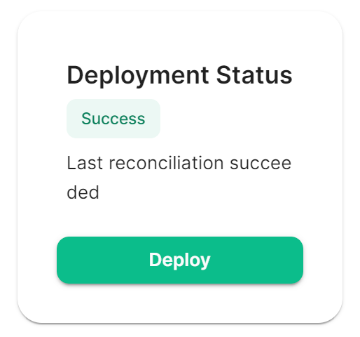
Once you have make the required changes to your Bridge.yml configuration, make sure you find and click the Save button at the bottom of the IRC Bridge configuration page to ensure your changes are updated.

You will then need to re-Deploy for any changes to take effect, as above ensure all changes made are saved then click Deploy.
Using the Bridge
For usage of the IRC Bridge via it's bot user see Using the Matrix IRC Bridge documentation, or for end user focused documentation see Using the Matrix IRC Bridge as an End User.
If you have setup mapping of rooms in your Bridge.yml, some rooms will already be connected IRC, users need only join the bridged room and start messaging. IRC users should see Matrix users in the Channel and be able to communicate with them like any other IRC user.
Setting Up the SIP Bridge
Configuring SIP bridge
Basic config
From the Installer's Integrations page, click "Install" under "SIP Bridge"
For the provided sipbridge.yml, please see the following documentation:
- `postgres_create_in_cluster`: `true` to create the postgres db into the k8s cluster. On a standalone deployment, it is necessary to define the `postgres_data_path`.
- `postgres_fqdn`: The fqdn of the postgres server. If using `postgres_create_in_cluster`, you can choose the name of the workload.
- `postgres_data_path`: "/mnt/data/sipbridge-postgres"
- `postgres_port`: 5432
- `postgres_user`: The user to connect to the db.
- `postgres_db`: The name of the db.
- `postgres_password`: A password to connect to the db.
- `port_type`: `HostPort` or `NodePort` depending on which kind of deployment you want to use. On standalone deployment, we advise you to use `HostPort` mode.
- `port`: The port on which to configure the SIP protocol. On `NodePort` mode, it should be in kubernetes range:
- `enable_tcp`: `true` to enable TCP SIP.
- `pstn_gateway`: The hostname of the PSTN Gateway.
- `external_address`: The external address of the SIP Bridge
- `proxy` : The address of the SIP Proxy
- `user_agent`: A user agent for the sip bridge.
- `user_avatar`: An MXC url to the sip bridge avatar. Don't define it if you have not uploaded any avatar.
- `encryption_key`: A 32 character long secret used for encryption. Generate this with `pwgen 32 1`
Setting Up the XMPP Bridge
Configuring the XMPP Bridge
The XMPP bridge relies on the xmpp "component" feature. It is an equivalent of matrix application services. You need to configure an XMPP Component on an XMPP Server that the bridge will use to bridge matrix and xmpp user.
On the hosting machine
From the Installer's Integrations page, click "Install" under "XMPP Bridge".
Examples
In all the examples below the following are set:
- The
domain_nameis your homeserver domain ( the part after : in your MXID ) :example.com - XMPP Server FQDN: xmpp.example.com
- XMPP External Component/
xmpp_domain:matrix.xmpp.example.com
Prosody Example
If you are configuring prosody, you need the following component configuration (for the sample xmpp server, matrix.xmpp.example.com):
    Component "matrix.xmpp.example.com"
        ssl = {
          certificate = "/etc/prosody/certs/tls.crt";
          key = "/etc/prosody/certs/tls.key";
        }
      component_secret = "eeb8choosaim3oothaeGh0aequiop4ji"
And then with that configured, you would pass the following into xmpp.yml:
xmpp_service: xmpp://xmpp.example.com:5347
xmpp_domain: "matrix.xmpp.example.com" # external component subdomain
xmpp_component_password: eeb8choosaim3oothaeGh0aequiop4ji # xmpp component password
Note: We've used pwgen 32 1 to generate the component_secret.
Joining an XMPP Room
Once you have the XMPP bridge up, you need to map an XMPP room to a Matrix ID. For example, if the room on XMPP is named: #welcome@conference.xmpp.example.com, where conference is the FQDN of the component hosting rooms for your XMPP instance, then on Matrix, you would join:
#_xmpp_welcome_conference.xmpp.example.com:example.com
So you can simply send the following command in your Element client to jump into the XMPP room via Matrix
/join #_xmpp_welcome_conference.xmpp.example.com:example.com
Joining a Matrix room from XMPP
If the Element/Matrix room is public you should be able to query the room list at the external component server address (Ex: matrix.xmpp.example.com)
The Matrix room at alias #roomname:example.com maps to #roomname#example.com@matrix.xmpp.example.com on the XMPP server xmpp.example.com if your xmpp_domain: matrix.xmpp.example.com
Note: If the Matrix room has users with the same name as yor XMPP account, you will need to edit you XMPP nickname to be unique in the room
| Element | XMPP | |
|---|---|---|
| #roomname:element.local (native Matrix room) | → | #roomname#element.local@element.xmpp.example.com (bridged into XMPP) |
| #_xmpp_roomname_conference.xmpp.example.com:element.local (bridged into Matrix/Element) | ← | #roomname@conference.xmpp.example.com (native XMPP room) |
Using the bridge as an end user
For end user documentation you can visit the Using the Matrix XMPP Bridge as an End User documentation.
Setting up Location Sharing
Overview
The ability to send a location share, whether static or live, is available without any additional configuration.
However, when receiving a location share, in order to display it on a map, the client must have access to a tile server. If it does not, the location will be displayed as text with coordinates.
By default, location sharing uses a MapTiler instance and API key that is sourced and paid for by Element. This is provided free, primarily for personal EMS users and those on Matrix.org.
If no alternate tileserver is configured either on the HomeServer or client then the mobile and desktop applications will fall back to Element's MapTiler instance. Self-hosted instances of Element Web will not fall back, and will show an error message.
Using Element's MapTiler instance
Customers should be advised that our MapTiler instance is not intended for commercial use, it does not come with any uptime or support SLA, we are not under any contractual obligation to provide it or continue to provide it, and for the most robust privacy customers should either source their own cloud-based tileserver or self-host one on-premises.
However, if they wish to use our instance with Element Web for testing, demonstration or POC purposes, they can configure the map_style_url by adding extra configurations in the advanced section of the Element Web page in the installer:
{
   "map_style_url": "https://api.maptiler.com/maps/streets/style.json?key=fU3vlMsMn4Jb6dnEIFsx"
}
Using a different tileserver
If the customer sources an alternate tileserver, whether from MapTiler or elsewhere, you should enter the tileserver URL in the extra_client section of the Well-Known Delegation Integration accessed from the Integrations page in the Installer:
{
... other info ...
"m.tile_server": {
"map_style_url": "http://mytileserver.example.com/style.json"
}
Self-hosting a tileserver
Customers can also host their own tileserver if they wish to dedicate the resources to doing so. Detailed information on how to do so is available here.
Changing permissions for live location sharing
By default live location sharing is restricted to moderators of rooms. In direct messages, both participants are admins by default so this isn't a problem. However this does impact public and private rooms. To change the default permissions for new rooms the following Synapse additional configuration should be set
default_power_level_content_override:
  private_chat:
    events:
      "m.beacon_info": 0
      "org.matrix.msc3672.beacon_info": 0
      "m.room.name": 50
      "m.room.power_levels": 100
      "m.room.history_visibility": 100
      "m.room.canonical_alias": 50
      "m.room.avatar": 50
      "m.room.tombstone": 100
      "m.room.server_acl": 100
      "m.room.encryption": 100
  # Not strictly necessary as this is used for direct messages, however if additional users are later invited into the room they won't be administrators
  trusted_private_chat:
    events:
      "m.beacon_info": 0
      "org.matrix.msc3672.beacon_info": 0
      "m.room.name": 50
      "m.room.power_levels": 100
      "m.room.history_visibility": 100
      "m.room.canonical_alias": 50
      "m.room.avatar": 50
      "m.room.tombstone": 100
      "m.room.server_acl": 100
      "m.room.encryption": 100
  public_chat:
    events:
      "m.beacon_info": 0
      "org.matrix.msc3672.beacon_info": 0
      "m.room.name": 50
      "m.room.power_levels": 100
      "m.room.history_visibility": 100
      "m.room.canonical_alias": 50
      "m.room.avatar": 50
      "m.room.tombstone": 100
      "m.room.server_acl": 100
      "m.room.encryption": 100
Removing Legacy Integrations
Today, if you remove a Yaml integration's config, its components will not be removed from the cluster automatically. You will also need to manually remove the custom resources from the Kubernetes cluster.
Removing Monitoring stack
You need to delete first the VMSingle and the VMAgent from the namespace :
kubectl delete vmsingle/monitoring -n <monitoring ns>
kubectl delete vmagent/monitoring -n <monitoring ns>
Once done, you can delete the namespace : kubectl delete ns/<monitoring ns>
Setting up Sliding Sync
Introduction to Sliding Sync
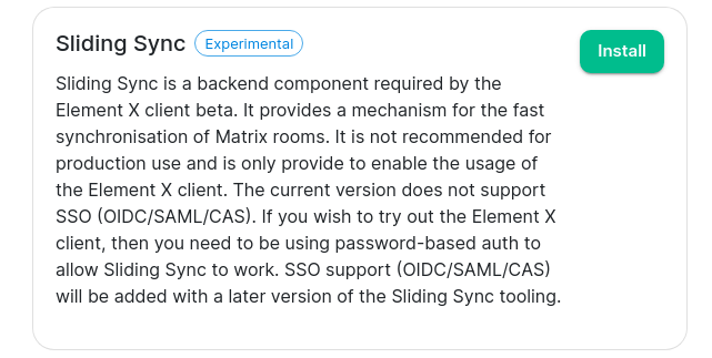
Sliding Sync is a backend component required by the Element X client beta. It provides a mechanism for the fast synchronisation of Matrix rooms. It is not recommended for production use and is only provide to enable the usage of the Element X client. The current version does not support SSO (OIDC/SAML/CAS). If you wish to try out the Element X client, then you need to be using password-based auth to allow Sliding Sync to work. SSO support (OIDC/SAML/CAS) will be added with a later version of the Sliding Sync tooling.
Installing Sliding Sync
From the integrations page, simply click the install button next to Sliding Sync:
This will take you to the following page:
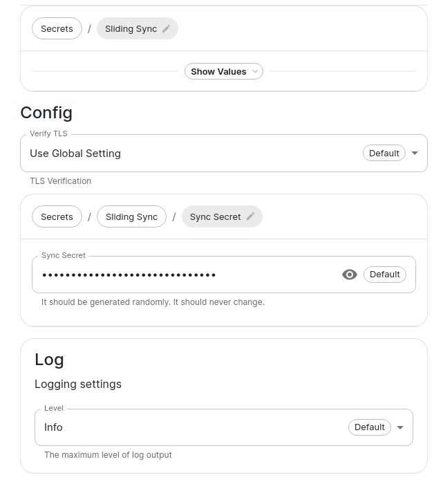
You should be able to ignore both the sync secret and the logging, but if you ever wanted to change them, you can do that here.
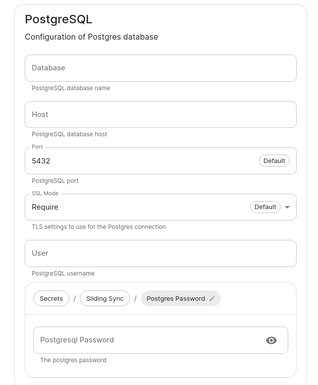
If you are using an external PostgreSQL database, then you will need to create a new database for sliding sync and configure that here:
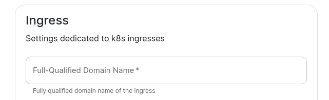
You will also need to set two values in the "Advanced" section -- the FQDN for sliding sync:
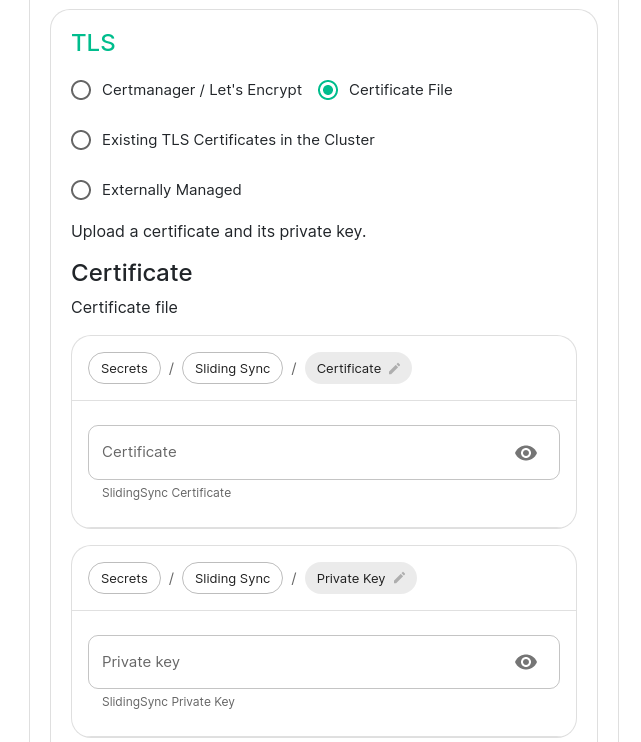
and the certificates for serving that FQDN over SSL:
Setting up Element Call
Introduction
Element Call is Element's next generation of video calling, set to replace Jitsi in the future. Element Call is currently an experimental feature so please use it accordingly; it is not expected to replace Jitsi yet.
How to set up Element Call
Required domains
In addition to the core set of domains for any ESS deployment, an Element Call installation on ESS uses the following domains:
- Required:
- Element Call Domain: the domain of the Element Call web client.
- Element Call SFU Domain: the domain of the SFU (Selective Forwarding Unit) for forwarding media streams between call participants.
- Optional:
- Coturn Domain: the domain of a Coturn instance hosted by your ESS installation. Required for airgapped environments.
Ensure you have acquired DNS records for these domains before installing Element Call on your ESS instance.
Required ports
Ensure that any firewalls in front of your ESS instance allow external traffic on the following ports:
- Required:
-
443/tcpfor accessing the Element Call web client. -
30881/tcpand30882/udp, for exposing the self-hosted Livekit SFU.
-
- Optional:
-
80/httpfor acquiring LetsEncrypt certificates for Element Call domains. - UDP (and possibly TCP) ports you choose for STUN TURN and/or the UDP relay of a self-hosted Coturn.
-
Basic installation
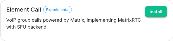
In the Admin Console, visit the Configure page, select Integrations on the left sidebar, and select Element Call (Experimental).
On the next page, the SFU > Networking section must be configured. Read the descriptions of the available networking modes to decide which is appropriate for your ESS instance.
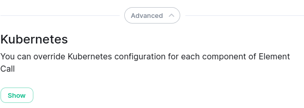
Next, click the Advanced button at the bottom of the page, then to show the Kubernetes section, then click the Show button in that section.
In the section that appears, configure the Ingress and Ingresses > SFU sections with the Element Call Domain and Element Call SFU Domain (respectively) that you acquired earlier, as well as their TLS sections to associate those domain names with an SSL certificate for secure connections.
Other settings on the page may be left at their defaults, or set to your preference.
How to set up Element Call for airgapped environments
Your ESS instance must host Coturn in order for Element Call to function in airgapped environments. To do this, click Install next to Coturn from the integrations page.

On the Coturn integration page, set the External IP of your ESS instance that clients should be able to reach it at, the Coturn Domain, and at least STUN TURN.
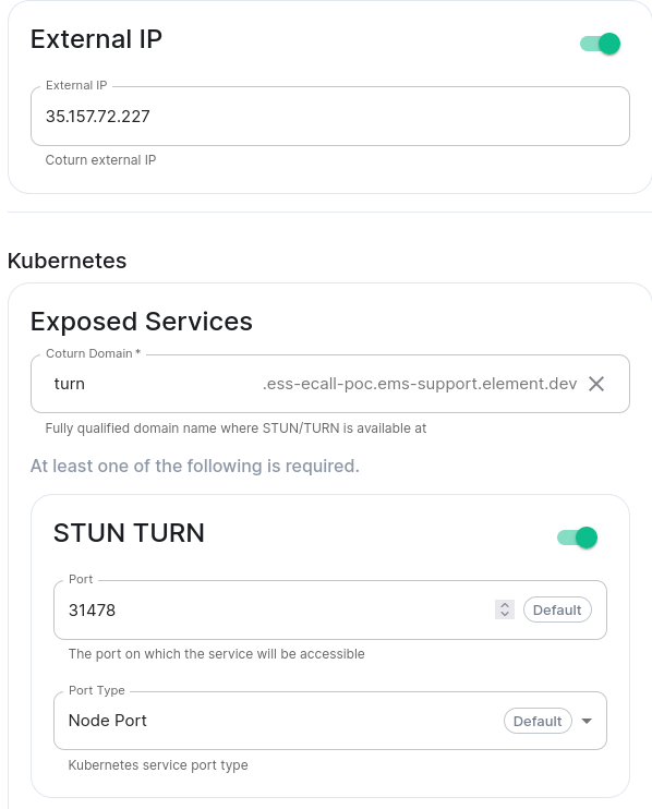
Then, within the Element Call integration page, ensure SFU Networking has no STUN Servers defined. This will cause the deployed Coturn to be used by connecting users as the STUN server to discover their public IP address.
Element Call with guest access
By default, Element Call shares the same user access restrictions as the Synapse homeserver. This means that unless Synapse has been configured to allow guest users, calls on Element Call are accessible only to Matrix users registered on the Synapse homeserver. However, enabling guest users in Synapse to allow unregistered access to Element Call opens up the entire homeserver to guest account creation, which may be undesirable.
To solve the needs of allowing guest access to Element Call while blocking guest account creation on the homeserver, it is possible to grant guess access via federation with an additional dedicated homeserver, managed by an additional ESS instance. This involves a total of two ESS instances:
- The main instance: an existing fully-featured ESS instance where registered accounts are homed & all integrations, including Element Call, are installed. Has Synapse configured with closed or restricted registration.
- The guest instance: an additional ESS instance used only to host guest accounts, and to provide its own deployment of Element Call for unregistered/guest access. Has Synapse configured with open registration.
Guest access to Element Call is achieved via a closed federation between the two instances: the main instance federates with the guest instance and any other homeservers it wishes to federate with, and the guest homeserver federates only with the main instance. This allows unregistered users to join Element Call on the main instance by creating an account on the guest instance with open registration, while preventing these guest accounts from being used to reach any other homeservers.
How to set up Element Call with guest access
- Install Element Call on your existing ESS instance by following the prior instructions on this page. This will be your main instance.
- Prepare another ESS instance, then follow the prior instructions to install Element Call on it. This will be your guest instance.
-
Set custom images for Element Web and Element Call:
- Log into each instance via SSH and follow these steps:
- Save a file with the following content:
- on the main instance:
apiVersion: v1 kind: ConfigMap metadata: name: element-call-main-overrides namespace: element-onprem data: images_digests: | element_web: element_web: image_repository_server: docker.io image_repository_path: vectorim/element-web image_tag: develop image_digest: sha256:0c5a025a4097a14f95077befad417f4a5af501cc2bc1dbda5ce0b055af0514eb- on the guest instance:
apiVersion: v1 kind: ConfigMap metadata: name: element-call-guest-overrides namespace: element-onprem data: images_digests: | element_call: element_call: image_repository_server: ghcr.io image_repository_path: element-hq/element-call image_tag: latest-ci image_digest: sha256:a9fbf8049567c2c11b4ddf8afbf98586a528e799d7f95266c7ae2ed16f250a56 - Run
kubectl -n element-onprem apply -f <path-to-saved-file>
- Save a file with the following content:
- In the admin console of each instance:
- Set
Cluster > Advanced > Config > Image Digests Config Mapto:-
element-call-main-overrideson the main instance -
element-call-guest-overrideson the guest instance
-
- In
Synapse > Advanced > Additional, add this YAML content:
experimental_features: msc3266_enabled: true - Set
- Log into each instance via SSH and follow these steps:
- In the admin console of the main instance:
- In
Element Web > Advanced > Additional configuration, add this JSON content:
{ "features": { "feature_new_room_decoration_ui": true, "feature_ask_to_join": true }, "element_call": { "guest_spa_url": "https://<guest-instance-element-call-domain>" } }- To limit federation to only the guest instance, apply these settings in the
Synapsesection:- Set
Profile > Federation TypetoLimited - Set
Config > RegistrationtoClosed - Set
Advanced > Allow Listto include the the guest instance's Synapse Domain
- Set
- In
- In the admin console of the guest instance:
- To limit federation to only the main instance, apply these settings in the
Synapsesection:- Set
Profile > Federation TypetoLimited - Set
Config > RegistrationtoClosed - Set
Advanced > Allow Listto include the main instance's Synapse Domain
- Set
- In
Integrations > Element Call > Additional configuration, add this JSON content:
{ "livekit": { "livekit_service_url": "https://<main-instance-sfu-domain>" } } - To limit federation to only the main instance, apply these settings in the
Setting Up the Skype for Business Bridge
Configuring the Skype for Business Bridge
Domains and certificates
The first step in preparing a Skype for Business (S4B) Bridge is to assign it a hostname that other S4B Server deployments can connect to it via SIP federation. This requires configuring DNS records and obtaining a TLS certificate for that hostname, which can be any name of your choosing.
The hostname assigned to a S4B Bridge is also known as its "SIP domain", as it serves as the domain name of the virtual SIP server managed by the bridge for federating with S4B Servers. The rest of this guide refers to a bridge's SIP domain as <bridge-sipdomain>.
Once you've chosen a hostname to assign to your bridge, other S4B Servers must be able to resolve that hostname to the bridge's public IP address via DNS. The most straightforward way to achieve this is to obtain public DNS records for <bridge-sipdomain>. If obtaining public records is not an option, an S4B Server administrator may configure it with internal records instead (which is outside the scope of this guide).
The DNS records to obtain are as follows:
-
A/AAAA <bridge-sipdomain> <bridge-public-ip-address> -
SRV _sipfederationtls._tcp.<bridge-sipdomain> <any-priority> <any-weight> 5061 <bridge-sipdomain>(optional, but recommended)
You must also obtain a TLS certificate for <bridge-sipdomain>. It may be obtained from either a public CSA like Let's Encrypt, or by any PKI scheme shared between the bridge & any S4B Servers it must connect with.
Basic config
From the Installer's Integrations page, click "Install" under "Skype for Business Bridge".
The most important configuration options are under Advanced > Exposed Services, which is where to set the SIP domain & TLS certificates of the bridge:
-
Skype for Business Bridge Domain: set this to
<bridge-sipdomain> -
SIP:
- If your ESS deployment allows for the usage of Host Ports, set "Port" to
5060and "Port Type" to "Host Port". - Otherwise, you must configure a reverse proxy to redirect inbound traffic for port
5060to the port you choose to assign this setting to.
- If your ESS deployment allows for the usage of Host Ports, set "Port" to
-
SIPS: Same as above, but with a port of
5061. -
TLS: Choose "Certificate File" and upload the certificate & private key obtained for
<bridge-sipdomain>.
Configuring Skype for Business Server
In order for a S4B Server deployment to connect to your bridge, the deployment must first be configured with an Edge Server to support SIP federation & to explicitly allow federation with the SIP domain of the bridge.
This section describes how to modify an existing S4B Server deployment to federate with the bridge. It assumes that a functional S4B Server deployment has already been prepared; details on how to install a S4B Server deployment from scratch are out-of-scope of this guide.
Overview
To support SIP federation, a S4B Server deployment uses a pool of one or more Edge Servers to relay traffic from external SIP domains to the pool of internal servers that provide the core functionalty of the deployment, known as Front End Servers. This design is necessary because Front End Servers are meant to be run within the private network of a deployment, without access to external networks.
Edge Servers are also used as a proxy for allowing native S4B users to log in from outside the deployment's private network. Users who connect in this manner are known as "remote users".
Once equipped with an Edge Server, a S4B Server deployment must then be configured with which external SIP domains it may federate with. By default, traffic from all external SIP domains is blocked.
The S4B Bridge acts as a SIP endpoint with its own SIP domain. Thus, for it to connect to a S4B Server deployment, the deployment must not only be equipped with an Edge Server, but it must set the bridge's SIP domain as an "allowed" domain.
Below is a simple diagram of the network topology of a S4B Server deployment federated with a S4B Bridge:
external S4B clients <───> Edge Pool <───> S4B Bridge <~~~> Matrix homeserver <═══> Matrix clients
                               A                                  A
                               │                                  ╏
                               V                                  V
internal S4B clients <─> Front End Pool                     Matrix homeserver <═══> Matrix clients

<───>: SIP
<~~~>: Matrix Application Service API
<═══>: Matrix Client-Server API
<╍╍╍>: Matrix Federation API
This guide covers only the usecase of a single Front End Server and Edge Server. It is expected that similar instructions apply for multi-server pools, but that has not been tested.
Prerequisites
A S4B Server deployment must be prepared with least the following components in order for it to be capable of adding an Edge Server:
- A Windows Server host running a Skype for Business 2019 Standard Edition Front End Server
- A Windows Server host acting as a Domain Controller for all hosts in the deployment, and also acting as an internal Certificate Signing Authority (CSA) & DNS server for all hosts
- If a Domain Controller is not available to act as a CSA, you may use any alternative/custom PKI scheme of your choosing, as long as the root CA certificate is mutually trusted by all hosts.
- If a Domain Controller is not available to act as a DNS server, custom hostname mappings may instead be applied in the "hosts" file of all hosts, located at
C:\Windows\System32\drivers\etc\hosts.
Such a deployment will have set some hostnames, which are referred to elsewhere in this guide as follows:
-
<s4b-intdomain>: The domain name / Primary DNS Suffix of the S4B Server deployment -
<frnt>.<s4b-intdomain>: The internal FQDN of the Front End Server, where<frnt>is its host name -
<s4b-sipdomain>: The default SIP domain of the deployment (visible in the Topology Builder on the Front End Server)
Deploying the Edge Server
An Edge Server must be deployed on a standalone host within the private network of the S4B Server deployment. It cannot be collocated on the same host as the Front End Server (source).
The OS to install on the Edge Server's host must be either Windows Server 2019 or 2016. Other versions of Windows Server, even newer versions, will not work (source). It should also be the same version of Windows Server that is installed on the host running the Front End Server. The host must also be outside of the Active Directory domain of the deployment.
Assign the host with a name of your choosing, which will be referred to elsewhere in this guide as <edge>. The internal FQDN of the host is therefore <edge>.<s4b-intdomain>.
After installing the OS, ensure Internet connectivity and perform Windows Update. Then, use the Server Manager desktop app (which can be found in Windows Search) to install the prerequisites listed by the official S4B documentation. Do not install any components needed for a Front End Server, as they may interfere with Edge Server components. It is also recommended to not install IIS on the Edge Server, despite the official documention, as it interferes with VoIP functionality.
Next, install the Skype for Business Administrative Tools. You may use the same installation media that was used for installing the Front End Server. Otherwise, it may be obtained from this download link.
Running the installation media will install two programs, known as the Core Components: the Deployment Wizard and the Management Shell. When using the Deployment Wizard on the Edge Server's host, do not run any tasks related to Active Directory, which should have already been run on the Front End Server, and must be run only once for the entire deployment. It is also unnecessary to install the rest of the Administrative Tools, such as the Topology Builder, on the Edge Server host.
Network topology
The network interfaces of hosts within the deployment must be configured such that inbound external SIP traffic is handled solely by one interface of the Edge Server, and that traffic between the Edge and Front End Servers remains within the private network of the deployment.
The Edge Server needs at least two network interfaces:
- an external-facing interface for accepting inbound SIP traffic
- Its default gateway must at least have a route to the IP address of your S4B Bridge instance.
- If the Edge Server host is behind NAT, inbound traffic must be routed to this interface.
- an internal-facing interface for reaching hosts within the private subnet of the deployment
- Its DHCP Server must be set to the internal IP address of the deployment's Domain Controller.
- This interface must not be routable to the public Internet.
Also, the firewall of the Edge Server must at least leave port 5061 open, and have it accessible to either the public Internet, or to the public IP address of your S4B Bridge host.
The Front End server needs at least one network interface, and for it to be an internal-facing interface with the same properties of the Edge Server's internal-facing interface. If Internet connectivity is desired (like for facilitating Phone Access & Meeting URLs), add a separate external-facing interface for handling external traffic, instead of making the internal-facing interface publicly routable.
The IP addresses of these interfaces are referred to elsewhere in this guide as follows:
-
<edge-extaddr>: the address of the Edge Server's external-facing interface -
<edge-intaddr>: the address of the Edge Server's internal-facing interface -
<frnt-intaddr>: the address of the Front End Server's internal-facing interface
DNS records
Internal records
The deployment needs an internal DNS record for the Edge Server's internal-facing interface in order to identify it by name. To add this record, open the DNS Manager on the Domain Controller host, and add an A/AAAA record for <edge>.<s4b-intdomain>, the FQDN of the Edge Server host, with the target address set to <edge-intaddr>.
External records
In order for your S4B Bridge to reach your Edge Server, acquire these public DNS records for advertising the SIP domain of your S4B Server deployment:
-
A/AAAA <edge>.<s4b-sipdomain> <edge-extaddr> -
CNAME sip.<s4b-sipdomain> <edge>.<s4b-sipdomain> -
SRV _sipfederationtls._tcp.<s4b-sipdomain> <any-priority> <any-weight> 5061 <edge>.<s4b-sipdomain>
Topology configuration
The topology of your S4B Server deployment may now be updated to include the Edge Server.
On the Front End Server, open the Topology Builder. Choose the option to download the current topology to a file, as this will ensure that you will edit an up-to-date version of the topology in the following steps.
Once the topology is loaded, navigate through the tree list on the left of the window to find the "Edge pools" entry (under "Skype for Business" > "site" > "Skype for Business Server 2019" > "Edge Pools"), right click it, select "New Edge Pool...", and apply the following settings in the wizard that appears:
- Pool FQDN: set to
<edge>.<s4b-intdomain> - Enable "This pool has one server"
- Enable federation (port 5061)
- Use a single FQDN and IP address
- Apply IPv4/6 settings so that you will be able to use the Edge Server's internal & external interface addresses later.
- External FQDN: set to
<edge>.<s4b-sipdomain> - Leave service ports at their default of 5061, 444, and 443 for Access, Web Conferencing, and A/V Edge Services respectively
- Internal & external IPv4/6 addresses: set these to addresses of the internal & external interfaces you set up earlier. The internal interface is never 127.0.0.1.
- Next hop pool & media association: set this to the Front End Server (which should be the only choice)
Next, in the settings for your site (available by right-clicking the tree entry immediately below the top-level "Skype for Business Server" item and choosing "Edit Properties"), enable:
- Apply federation route assignments to all sites
- Enable SIP federation, and choose your Edge Server
All required topology changes have now been set. To apply these changes onto the Front End Server:
The toplogy must next be published onto the Edge Server. To do so:
- On the Front End Server, open the S4B Management Shell, and export the topology to a file with this command:
-
Export-CsConfiguration -FileName <path\to\file>
-
- Copy that file onto the Edge Server. Ideally export the file to a shared drive so that a manual copy is unnecessary.
- On the Edge Server, open the Deployment Wizard, click "Install or Update Skype for Business Server System", and execute the "Install Local Configuration Store" step. Choose the option to "import from a file (recommended for Edge Servers)", and select the file for the exported topology configuration.
- While still in the Deployment Wizard, execute the "Setup or Remove Skype for Business Server Components" step.
Certificates
S4B sends/receives all SIP traffic over TLS; thus, the Edge Server needs its own set of certificates, both internal & external to the S4B Server deployment.
To obtain all required certificates, open the Deployment Wizard on the Edge Server, click "Install or Update Skype for Business Server System", and execute the "Request, Install or Assign Certificates" task. This will display the Certificate Wizard, which shows a list of all required certificates, and which services they must contain the domain names of. Only two certificates should be listed: "Edge internal" and "External Edge certificate (public Internet)".
The "Edge internal" certificate should be obtained by sending a certificate signing request to the Domain Controller in your deployment, which acts as an internal Certificate Signing Authority. To do so, click the "Edge internal" entry in the list, then click the Request button on the right edge of the window. This will display a dialog that guides you through the steps of sending the request. Once the request is sent, enter the Domain Controller, accept the request, and then go back to the Edge Server to assign the approved certificate.
In contrast, the "External Edge certificate" must be provided by a Certificate Authority that is trusted by the host running the S4B Bridge. This may be a public CA such as Let's Encrypt, or any custom PKI scheme of your choosing. If using the latter, ensure that the root CA's certificate is installed on both the Edge Server host and the S4B Bridge host.
The "External Edge certificate" must contain these names:
- Subject Name:
<edge>.<s4b-sipdomain> - Subject Alternative Names:
- DNS Name:
<edge>.<s4b-sipdomain> - DNS Name:
sip.<s4b-sipdomain>
- DNS Name:
Once the certificate is obtained, use the Certificate Wizard on the Edge Server to assign it.
Restart to apply changes
Changes to server topology requires restarting system services on both the Front End Server and Edge Server. To do so, open the Management Server on each server, and run these commands:
- Run
Stop-CsWindowsServiceon the Edge Server, and wait for it to complete. - Run
Stop-CsWindowsServiceon the Front End Server, and wait for it to complete. - Run
Start-CsWindowsServiceon the Front End Server, and wait for it to complete. - Run
Start-CsWindowsServiceon the Edge Server, and wait for it to complete.
Federation settings
With the topology in place, the S4B Server deployment may now be configured to allow federation with your S4B Bridge. Federation settings may be applied on the Front End Server either in the web admin panel at https://<frnt>.<s4b-intdomain>/macp, or via Powershell commands in the Management Shell. This section lists each setting that must be applied in the web admin panel, followed by its equivalent Powershell in the Management Shell.
Log into the admin panel using the credentials of your Windows account on the Front End Server, and expand the "Federation and External Access" section on the left sidebar. Then, navigate to the following sections and apply these settings:
- External Access Policy:
- In either the Global policy or a site-level policy for your S4B site:
- "Enable communications with federated users"
- Powershell:
- To edit the Global policy:
Set-CsExternalAccessPolicy -Identity Global -EnableFederationAccess $True - To create & configure a site-level policy:
New-CsExternalAccessPolicy -Identity Site:<your_site_name> -EnableFederationAccess $True
- To edit the Global policy:
- In either the Global policy or a site-level policy for your S4B site:
- Access Edge Configuration
- In Global policy (the only option available):
- "Enable federation and public IM connectivity"
- Optional: "Enable partner domain discovery": Enable this if you would rather have federation be managed dynamically instead of having to explicitly add the SIP domain of your bridge to your S4B Server's allowlist of federated domains. For this to work, you must register a DNS SRV record for your bridge's SIP domain (see the section on bridge domains and certificates). However, adding the bridge's domain to your S4B Server's allowlist is still necessary to prevent the bridge's traffic from being rate-limited.
- Powershell:
Set-CsAccessEdgeConfiguration -AllowFederatedUsers $True [-EnablePartnerDiscovery $True -DiscoveredPartnerVerificationLevel "AlwaysVerifiable"]
- In Global policy (the only option available):
- SIP Federated Domains
- add your S4B Bridge's SIP domain as an Allowed Domain:
- Domain name (or FQDN):
<bridge-sipdomain> - Access Edge service (FQDN):
- If you registered a DNS SRV record of
_sipfederationtls._tcp.<bridge-sipdomain>, leave this blank. - Otherwise, set this to
<bridge-sipdomain>.
- If you registered a DNS SRV record of
- Domain name (or FQDN):
- Powershell:
New-CsAllowedDomain -Identity "<bridge-sipdomain>" -Comment "<any-name-of-your-choice>"
- add your S4B Bridge's SIP domain as an Allowed Domain:
To verify any of these settings in Powershell, replace New- or Set- in any of the issued commands with Get-. To unapply a setting, use Remove-.
These changes may take some time before they get applied. When in doubt, restart all services by running Stop-CsWindowsService then Start-CsWindowsService in the S4B Server Management Shell on both the Front End Server and the Edge Server.
Contact mapping
Matrix users in S4B
Once a S4B Server is connected to an instance of the bridge, a Matrix user may be added to a S4B user's contact list as a "Contact Not in My Organization". The S4B desktop client provides this action via the "Add a contact" button, which is on the right edge of the main window just below the contact search bar.
Proceeding will display a prompt to set the IM Address of the contact to be added. Technically, an IM Address is a SIP address without the leading sip: scheme.
The IM Address of a Matrix user managed by the bridge is derived from the user's MXID, and has the following mapping:
@username:matrixdomain → username+homeserver@bridge-sipdomain
-
username: the "localpart" of the MXID. -
matrixdomain: the domain name of the Matrix user's homeserver. -
bridge-sipdomain: the SIP domain of the bridge (which may differ from the homeserver domain).
S4B users in Matrix
S4B users are represented in Matrix by virtual "ghost" users managed by the bridge. The MXID of a virtual S4B user is derived from the "Bridge > User Prefix" setting (from the bridge's Integrations configuration page in the Installer) and the IM Address (i.e. the SIP Address) of the virtual user's corresponding S4B user, and has the following mapping:
username@s4b-sipdomain → @<user-prefix>sip=3ausername=40s4b-sipdomain:matrixdomain
-
<user-prefix>: the value of "Bridge > User Prefix" from the bridge's configuration. The default value is_s4b_. -
sip=3a: the URL encoding of thesip:scheme of an IM Address (with an escape character of=instead of the typical%), encoded so as to not conflict with the:belonging to the MXID.- Note that despite S4B using TLS for all SIP traffic, the IM Addresses of S4B contacts never use the
sips:scheme.
- Note that despite S4B using TLS for all SIP traffic, the IM Addresses of S4B contacts never use the
-
username: the "localpart" of the IM Address. -
=40: the URL encoding of the@character of the IM address, encoded so as to not conflict with the@belonging to the MXID. -
s4b-sipdomain: the SIP domain of the S4B Server. -
matrixdomain: the domain name of the homeserver that the bridge is registered with.
Thus, with a <user-prefix> of _s4b_, the IM Address to MXID mapping is:
username@s4b-sipdomain → @_s4b_sip=3ausername=40s4b-sipdomain:matrixdomain